1
1
Device Structure
1.1
Device External Cable
Note:
The following figure is for reference only, which is used to know the function of cable port.
There are differences about cable structure between different models, please refer to the actual
product for more details.
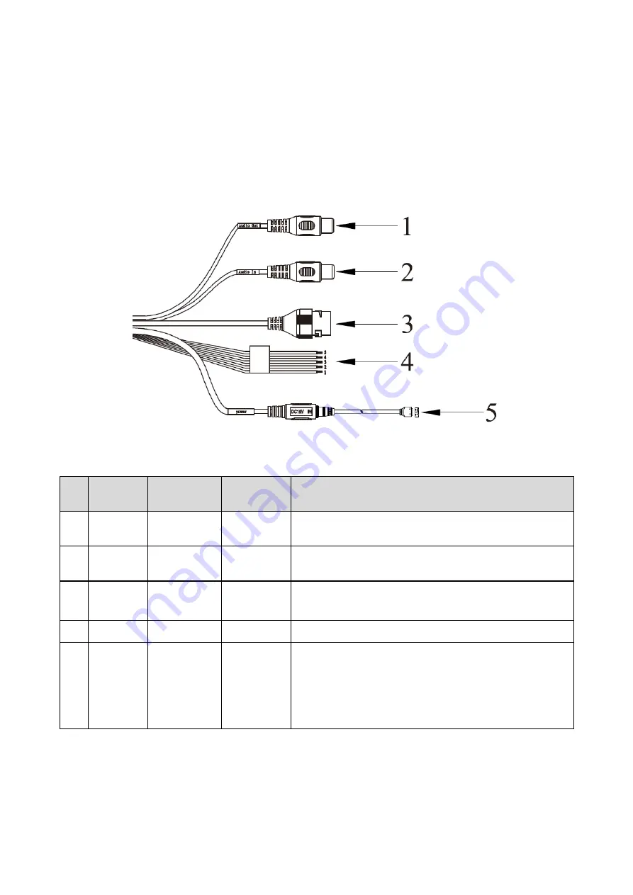
You can refer to the following figure for cable information. See Figure 1-1
Figure 1-1
Please refer to the following sheet for detailed information.
No. Port
Name
Function
Connector
Note
1
AUDIO
OUT
Audio
output port
RCA
Output audio signal to speaker and etc.
2
AUDIO
IN
Audio input
port
RCA
Input audio signal, receive analog audio signal from
pick up and etc.
3
LAN
Network
port
Ethernet
port
Connect to standard Ethernet cable.
Note: Some series don
’t support PoE.
4
I/O
I/O port
-
Alarm signal input/output.
5
Power
Power input
port
/
Power port. Input DC 12V or AC 24V power.
Note:
Please connect the DC5.5 round port to 2-pin
converter cable when you are using AC 24V power.
Please use according to device tag.
Please refer to the follow sheet for detailed pin information.
Available from A1 Security Cameras
www.a1securitycameras.com email: [email protected]


