background image


3  Network Configuration  

The IP address of all the cameras is the same when leaving factory (default IP192.168.1.108), in 

order to make the camera get access to the network smoothly, please plan the useable IP 

segment reasonably according to the actual network environment.  

3.1  Modify IP Address  

IP address can be acquired and modified through quick configuration tool for the cameras which 

are  accessed  via  wired  network,  it  needs  to  connect  wired  network  to  configure  wireless 

parameters before using wireless network cameras. In this chapter, it will introduce the approach 

of modifying IP address via 

“Quick Configuration Tool”; also you can modify the IP address in the 

network  parameters  of  the  WEB  interface,  please  refer  to  the  document  in  the  disk  <<  WEB 

Operation Manual>> for more details.  

Note:  

Currently  the  quick  configuration  tool  only  supports  the  cameras  which  apply  to  the  same 

network segment with computer IP address.  

Step 1 

Double click the “ConfigTools.exe” and open the quick configuration tool. 

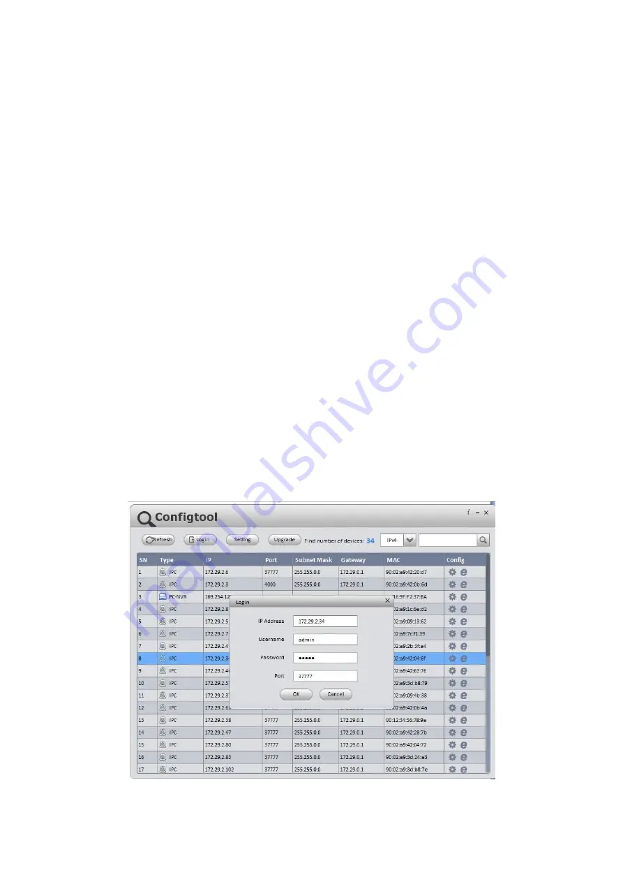
Step 2 Double click the device to be configured, the system will pop out the 

“Login” dialog box. 

Enter  the  IP  address,  user  name,  password  and  port  number  of  the  camera,  and  click 

“Confirm”. 

Note:  

The default user name and password are admin and admin respectively, the default of port is 

37777.  See Figure 3-1 for more details.  


Figure 3-1  

Step 3 Modify the camera IP address on the 

“Net” interface, click “Save” to finish modification.  

                 Available from A1 Security Cameras 

    www.a1securitycameras.com email: [email protected]

Summary of Contents for IPC-HFW81230E-Z

Page 1: ...Dahua HD IR Bullet Network Camera Quick Start Guide Version 1 0 0 Zhejiang Dahua Vision Technology Co LTD Available from A1 Security Cameras www a1securitycameras com email sales a1securitycameras com ...

Page 2: ...ssume no liability or responsibility for all the fires or electrical shock caused by improper handling or installation We are not liable for any problems caused by unauthorized modification or attempted repair 2 Environment Please don t aim the device at strong light such as lighting sunlight and so on to focus otherwise it may cause overexposure It is not the device malfunction which will affect ...

Page 3: ...mance of the device Dome cover is an optical device please don t touch or wipe cover surface directly during installation and use please refer to the following methods to deal with once dirt is found Stained with dirt Use oil free soft brush or hair dries to remove it gently Stained with grease or fingerprint Use soft cloth to wipe the water drop or oil gently to make it dry then use oil free cott...

Page 4: ...is encouraged to try to correct the interference by one or more of the following measures Reorient or relocate the receiving antenna Increase the separation between the equipment and receiver Connect the equipment into an outlet on a circuit different from that to which the receiver is connected Consult the dealer or an experienced radio TV technician for help FCC Information 3 FCC conditions This...

Page 5: ...etails check and download corresponding user s manual and tool Before installation please open the package and check all the components are included Contact your local retailer ASAP if something is broken in your package Accessory Name Amount Network Camera Unit 1 Quick Start Guide 1 Installation Accessories Bag 1 CD 1 Available from A1 Security Cameras www a1securitycameras com email sales a1secu...

Page 6: ...ernal Cable 1 1 2 Framework and Dimension 2 1 3 Alarm Setup 2 2 Device Installation 5 3 Network Configuration 9 3 1 Modify IP Address 9 3 2 Login WEB Interface 10 Available from A1 Security Cameras www a1securitycameras com email sales a1securitycameras com ...

Page 7: ...T Audio output port RCA Output audio signal to speaker and etc 2 AUDIO IN Audio input port RCA Input audio signal receive analog audio signal from pick up and etc 3 LAN Network port Ethernet port Connect to standard Ethernet cable Note Some series don t support PoE 4 I O I O port Alarm signal input output 5 Power Power input port Power port Input DC 12V or AC 24V power Note Please connect the DC5 ...

Page 8: ...m source 4 ALARM_IN2 Alarm input port 2 It is to receive the on off signal from the external alarm source 5 GND Ground port 1 2 Framework and Dimension Note The following figure is for reference only which is used to know the device dimension Please refer to the following figure for dimension information The unit is mm See Figure 1 2 Figure 1 2 1 3 Alarm Setup Note It is only supported by some ser...

Page 9: ...ice will generate signal of high and low level Set corresponding NO and NC inputs Step 4 Set alarm output on the WEB the alarm output is corresponding to the alarm output end of the device this is the alarm output port of the I O port cable Please refer to the following figure for alarm input and output information See Figure 1 4 Alarm input When the input signal is idle or grounded the device can...

Page 10: ...LM_OUT_GND form a switch which is used to provide alarm output Normally the switch is on it will be off when there is alarm output Figure 1 5 Available from A1 Security Cameras www a1securitycameras com email sales a1securitycameras com ...

Page 11: ...llation Optional You can see the SD installation card slot analog output two direction button and reset button after you open the lower cover Insert the SD card into the slot which is shown in Figure 2 2 you can press the SD card slightly to insert it because the card slot is elastic Figure 2 2 Available from A1 Security Cameras www a1securitycameras com email sales a1securitycameras com ...

Page 12: ...ten the 4 screws to fix the device on the installation surface wall or ceiling You can move the device sunshield back and forth When you have fixed the device you must tighten screws on sunshade Step 5 Plug the external cables of the device properly according to the use requirements Step 6 Adjust the monitoring direction of the device Note The location of the adjusting screw may be different due t...

Page 13: ...twork port waterproof connector and it is used outdoors Figure 2 4 1 Keep the convex groove outward and install the rubber ring into the network port keep the smaller hole of the rubber ring outward and install the fixing rubber ring into the main body of the waterproof connector 2 Pull the network cable without crystal head through main body of waterproof connector fixing rubber ring and waterpro...

Page 14: ...twork port and waterproof connector firmly 4 Put the waterproof locking cover on the main body of waterproof connector and rotate it clockwise to lock the waterproof connector and waterproof locking cover firmly Available from A1 Security Cameras www a1securitycameras com email sales a1securitycameras com ...

Page 15: ...ress in the network parameters of the WEB interface please refer to the document in the disk WEB Operation Manual for more details Note Currently the quick configuration tool only supports the cameras which apply to the same network segment with computer IP address Step 1 Double click the ConfigTools exe and open the quick configuration tool Step 2 Double click the device to be configured the syst...

Page 16: ...ual in the disk and the actual interface for more details Step 1 Open IE and input the modified camera IP address in the address bar Step 2 The login interface is shown below please input your user name and password Default user name is admin and password is admin respectively click login See Figure 3 3 for more details Available from A1 Security Cameras www a1securitycameras com email sales a1sec...

Page 17: ... system prompt see Figure 3 4 for the WEB main interface Please modify the administrator password as soon as possible after you successfully logged in Figure 3 4 Available from A1 Security Cameras www a1securitycameras com email sales a1securitycameras com ...

Page 18: ...ersy please refer to the final explanation of us Please visit our website or contact your local service engineer for more information Dahua Technology Co Ltd Address No 1199 Bin an Road Binjiang District Hangzhou PRC Postcode 310053 Tel 86 571 87688883 Fax 86 571 87688815 Email overseas dahuatech com Website www dahuasecurity com Available from A1 Security Cameras www a1securitycameras com email s...

Reviews: