


8.Features
© 2023 China Daheng Group, Inc. Beijing Image Vision Technology Branch 124
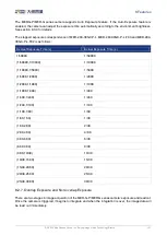
Input Signal
Trigger Delay
Valid Signal
Delay Time
1000ms
Figure 8-2 Trigger delay schematic diagram
4)
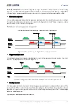
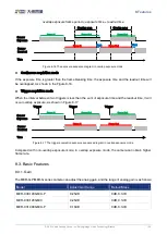
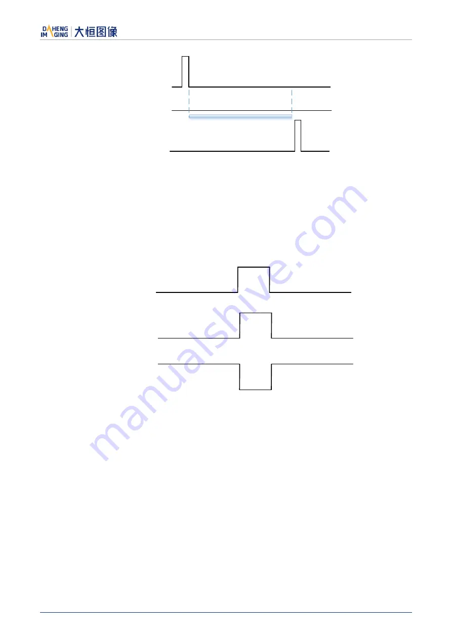
Input Inverter
The signal level of input lines is configurable for the MER-G-P/MER-G series camera. The user can select
whether the input level is reverse or not by setting "LineInverter".
For the MER-G-P/MER-G series camera, the default input line level is False when the camera is powered
on, indicating that the input line level is not reversed. If it is set as True, indicating that the input line level
is reversed. As shown in the Figure 8-3:
Input Signal
Input Line
LineInverter=
False
Input Line
LineInverter= True
Figure 8-3 Setting input line reverse
8.1.2.
Output Mode Operation
1)
Configuring Line as output
The MER-G-P/MER-G series camera has three output signals: Line1, Line2, and Line3. In which the Line1
is a uni-directional opto-isolated output I/O, Line2 and Line3 are bi-direction configurable I/Os.
The camera's default output is Line1 when the camera is powered on. Line2 and Line3 can be configured
to be output by changing the "LineMode" of this line.
Each output source of the three output lines can be configurable, and the output source includes: Strobe,
UserOutput0, UserOutput1, UserOutput2.
The default output source of the camera is UserOutput0 when the camera is powered on.


