background image

Chapter 2   

Embroidery Guide


14 

     Owner’s Manual of BECS- A15 Computerized Control System 


No. 

Icon 

Name 

Description 

Reference Page 

13 


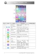
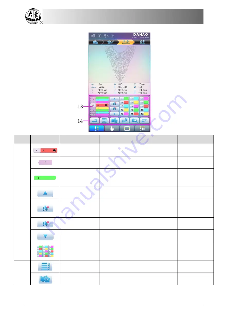
Current Operation 
Position 

Set, insert or delete needle bar number 
here. 


Color 

Lump 

Number List 

Display the color lump  number of the 
pattern 


Needle Bar 
Number and Color 

Display the needle bar number and 
needle bar thread color of the 
corresponding color lump 


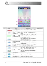
Move Up 

Move up the color-changing list in order to 

select the color lump to be set 


Insert Needle Bar 
Number 

Press this key and then press needle bar 
number to insert it to the current needle 
bar number list 


Delete Needle Bar 
Number 

Delete the current needle bar number 
from the needle bar number list 


Move Down 

Move down the color-changing list in 

order to select the color lump to be set 


Needle Bar


Number Color 

Selection Area 

Select the color for the selected needle 
bar number 


14 


Repetition   

Repeat the color-changing order 


Patch Embroidery 

Set as patch embroidery pattern 


Summary of Contents for BECS-A15

Page 1: ...Computerized Embroidery Machine Controller BECS A15 General Part Version 2019 03 OWNER S MANUAL http www dahaobj com en sh asp...

Page 2: ...ocedure of Embroidery 15 2 4 Normal Embroidery Returning and Patching 19 2 5 Embroidery Operation 19 2 6 Thread Breakage Detection 19 2 7 Working Status 20 Chapter 3 U Disk Management 22 3 1 Select U...

Page 3: ...ngs of Color Changing Order 35 4 2 3 Set Needle Bar Color 35 Chapter 5 Settings of Embroidery Parameters 37 5 1 Procedure for Setting General Parameters 38 5 2 Instruction on Some Functions within Gen...

Page 4: ...ter Pattern Operation 55 7 1 Enter Main Interface for Letter Embroidery 55 7 2 Input Letter String for Embroidery 55 7 3 Adjust Letter Pattern 56 7 4 Save Letter Pattern 60 Chapter 8 Assistant Operati...

Page 5: ...it Sequin Design 74 10 5 Setting of Multi Sequin Embroidery Parameters 79 10 6 Manual Operation of Sequin Embroidery 81 10 7 Debugging Multi Sequin Embroidery 81 10 8 Sequin Mending 82 Chapter 11 Oper...

Page 6: ...ons of Clamp Foot 93 12 5 Debugging Special Embroidery 93 12 6 Steps on Special Embroidery 94 12 7 Mechanical Category and Driving Mode Selection for Special Embroidery Machines 94 Chapter 13 Online U...

Page 7: ...to humidity gas poisonous gas water and dust Forbidden Don t store or operate the machine in the vibration area which may cause trouble to the machine Attention Please abide all the warnings and safe...

Page 8: ...cables Make sure each turning point of cable is well protected Add shelter pipes to increase insulating capability if necessary Attention must be grounded The equipment grounding conductor should use...

Page 9: ...should have the machine checked before power on Matters for Attention on Rejection Attention Rejection should obey the rules and regulations set by national industrial electronic standards 1 2 Main Fe...

Page 10: ...de or stop code and when the machine embroiders to the patch point it will halt and move out frame for patching After sticking a patch user would press the start key to return the frame and continue e...

Page 11: ...g the Data of Selected Pattern to Generate New Pattern Users can compile any pattern according to zoom ratio rotate angle normal repetition or partial repetition to generate a new pattern and save it...

Page 12: ...top and give warning by indicator 21 Color changing At the color changing point user can either perform the color changing manually or let the system do it automatically according to the preset order...

Page 13: ...s machine uses the touching panel as its input device In order to extend the service life of the panel and to maintain its performance please don t apply too much pressure on the screen during operati...

Page 14: ...is pulled out the USB disk may be damaged permanently 2 2 Instruction of the Main Interface No Icon Name Description Reference Page 1 Network Connection Failure Status Network Status disconnected con...

Page 15: ...click this key for the operation of manual thread trimming including bobbin thread trimming Section2 3 Main Shaft Manual Adjustment After stop if the main shaft is not at the proper position press thi...

Page 16: ...lor changing At this moment user needs to perform manual color changing to shift to the needed needle position and press the start key for embroidery Return Return to the previous interface Main Shaft...

Page 17: ...authority management touch screen calibration and time management Chapter 9 Manual Color changing When machine stops at correct position the operation is valid press it to enter manual color changing...

Page 18: ...e or make analog display of pattern Letter Pattern Letter pattern and its parameter setting Pattern Deletion Used to delete selected patterns Pattern Output Used to transfer memory patterns to USB dis...

Page 19: ...n Reference Page Next Enter the next operation interface No Icon Name Description Reference Page 12 Common Parameter Setting User can adjust these parameters to control the final embroidery effect of...

Page 20: ...lump Move Up Move up the color changing list in order to select the color lump to be set Insert Needle Bar Number Press this key and then press needle bar number to insert it to the current needle bar...

Page 21: ...nput patternss through network or USB disk Only with successful registration displayed can it be possible to transmit patternss by network For U disk operation in pattern management interface press to...

Page 22: ...e frame center set by soft limitation 6 Set cyclic embroidery press to enter other function operation Press to enter parameter management interface Then press Embroidery Assistant Parameters and set c...

Page 23: ...time to move the frame in the direction of the angle bisector is the speed key for manual frame moving Press to shift between high speed and low speed 3 Clear the Frame Coordinates When the machine st...

Page 24: ...to enter idling interface where user can press to return the frame to origin 7 Back to Stop Point Press in the main interface to enter idling interface where user can press to return the frame to sto...

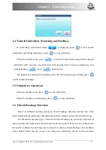
Page 25: ...ng press to start normal embroidery 2 5 Embroidery Operation When the machine stops press to start embroidery When the machine is embroidering press to stop embroidery 2 6 Thread Breakage Detection Ba...

Page 26: ...two can complement each other with their advantages which results in sensitive and stabilized detecting effect 2 7 Working Status There are three working statuses 1 Embroidery Ready Status preset para...

Page 27: ...mbroidery confirmation status where user can press start key again to enter embroidery running status In embroidery confirmation status is displayed in the main interface press and then press to confi...

Page 28: ...can be read by the system For data output patterns will be saved in the U disk as DSB format 3 1 Select U Disk Since the system supports several storage devices user need select the U disk for operati...

Page 29: ...nt page number and total page number Back to Upper Level Return to upper level 3 Basic Pattern Data Display the basic data of current pattern 4 Pattern Preview Load the selected pattern Check its deta...

Page 30: ...preview Pattern files and directories are shown in figure in the list One page of the list contains 8 items If the amount of the object within the current directory is more than 8 the object list will...

Page 31: ...the pattern For more information please refer to section 6 3 3 3 Pattern Input To input patterns within the U disk to the machine s memory user need select the pattern files to be inputted and then in...

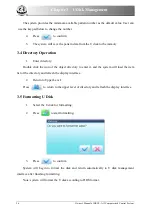
Page 32: ...tory Double click the icon of the object directory to enter it and the system will load the item list of the directory and refresh the display interface 2 Return to Upper Level Press to return to the...

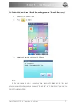
Page 33: ...attern file and directory 1 Select objects to be deleted 2 Press to delete 3 System will ask user to confirm the deletion Note If the user wants to delete a directory the system will delete all the fi...

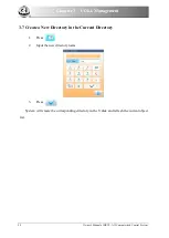
Page 34: ...nual of BECS A15 Computerized Control System 3 7 Create a New Directory in the Current Directory 1 Press 2 Input the new directory name 3 Press System will create the corresponding directory in the U...

Page 35: ...quently used parameters and color changing order in parameter setting interface and needle bar color changing order setting interface Since this system supports multi task operation user can set and m...

Page 36: ...will explain how to set the X Y Scale as an example and give the definitions of other parameters refer to 4 1 1 for setting method 4 1 1 Settings of X Y Scale This parameter controls the scaling perce...

Page 37: ...le for users to set respectively 2 Adjusting X Y Scales User can press number pad to modify the scaling rate at X direction press to cancel the last input digit and press to clear the input number 3 P...

Page 38: ...o modes rotation prior to scaling and scaling prior to rotation When user has set the parameters Scale X Y and Rotate Angle the patterns will rotate first and then scale up down if rotation prior to s...

Page 39: ...mes is 2 The largest set value is 99 99 4 1 8 X Y Rep Interval The above picture has explained the meaning 4 2 Settings of Color changing Order 4 2 1 Color changing Interface No Icon Name Description...

Page 40: ...or Selection Area Select the color for the needle bar number to be set 5 Return Return to the previous operation interface Repetition Repeat color changing order Patch Embroidery Set the patch embroid...

Page 41: ...want to view and then press to jump to the color block 4 To change a certain needle bar number press to move to the item to be modified and then press the new needle bar number 5 To insert a new needl...

Page 42: ...ce 3 To set the needle bar color select the needle bar first and then select the color from the 45 default color lumps The corresponding color of the needle bar button will be refreshed 4 Press to sav...

Page 43: ...ettings of Embroidery Parameters Parameters are grouped according to different functions see Appendix 1 Parameter List Press in the main interface and press for user or for specialist to enter paramet...

Page 44: ...similar for each general parameter You can follow the guide of this section to set all parameters 1 Select Parameter Type User can use the keys at the bottom of the screen parameter type key and page...

Page 45: ...er the front fabric again and at this time it s possible for user to replace the back one 5 2 2 Brake Adjustment A Must for New Machine This function is to adjust the control parameters for braking so...

Page 46: ...attern management interface The memory patterns management interface contains patterns image display area navigation and pagination area information area and management operation area The patterns ima...

Page 47: ...ry and its parameters Delete Pattern Delete the selected pattern Pattern Output Save the memory pattern to U disk Home U Disk Management Press it to enter U disk management interface to make related o...
Page 48: ...g paragraphs for detailed explanation Press or to turn page and press to return to memory pattern management interface 6 2 Select Pattern for Embroidery 1 Press to enter memory pattern management inte...
Page 49: ...p Move the pattern upwards Single Step Display Draw the pattern by drawing single steps Scale up Enlarge the pattern in the preview area Scale down Reduce the pattern in the preview area Actual Displa...

Page 50: ...Press to enter memory pattern management interface 2 Select a pattern in the memory pattern image display area 3 Press to open memory pattern preview interface 4 Press to control the size of the patt...

Page 51: ...Control System 45 4 System will display the window to Select U disk and press to make the selection 4 Input the pattern name saved in the U disk The system provides the minimum available pattern numb...

Page 52: ...ement interface 2 Select a pattern in the memory pattern image display area 3 Press to enter memory operation selection interface 4 Click Copy Pattern to enter its operation interface The system will...

Page 53: ...rol System 47 6 To change the new pattern name click New Pattern name and input the new name in the pop up window 7 Press to copy the pattern and return to pattern operation selection interface Press...

Page 54: ...ress to quit the creating operation and return to pattern operation selection interface 6 7 Create High speed Pattern This function can be used to devide long stitch into short ones so as to prevent s...

Page 55: ...ew pattern number and name instead of default ones 6 Press Divide Stitch to input the stitch number of the division position 7 Press to divide the pattern into two new patterns and return to pattern o...

Page 56: ...tern and return to pattern operation selection interface Press to quit the creating operation and return to pattern operation selection interface 6 10 Mosaic Pattern This operation is to combine two p...

Page 57: ...ern means a pattern group combined from several certain less than 99 memory patterns after setting their parameters The combined pattern is set as automatic continuous embroidery To embroider a combin...

Page 58: ...al amount of patterns 5 Set the parameters of the first pattern including pattern number scaling ratio rotating angle pattern direction and priority mode Please refer to Chapter 4 for details of the s...

Page 59: ...53 7 Press to enter the operation interface The system will hint user to input the new pattern number and the new pattern name 8 Press to save the combined pattern and return to pattern operation sel...

Page 60: ...ry pattern image display area 3 Press to enter memory operation selection interface 4 Press Satin Stitch Adjustment to enter the operation interface 5 User can press to input new pattern number and na...

Page 61: ...m can generate letter pattern based on the built in font libraries 7 1 Enter Main Interface for Letter Embroidery Press in the pattern management interface to enter the main interface for letter embro...

Page 62: ...m The upside of the window is the display area and the downside is the operation area After inputting the letter string press to save 7 3 Adjust Letter Pattern 1 Letter Pattern Adjustment Interface Th...

Page 63: ...cted Letters Letter String edit letter string Change Font change the font of selected letters Press this key to display a dialog box where user can select a desired font and confirm it Color changing...

Page 64: ...ing Press this key to display thedensity dialog box where user can set stitch form increase or decrease density Stitch Form show hide the stitch form Hiding the stitch form can improve operation speed...

Page 65: ...commended to be changed then press confirmation key to start saving Exit quit from Create Letter Pattern 4 Keys for Adjusting Whole Arrangement If you adjust the parameters for whole rank after the ed...

Page 66: ...rc Reduce Radian when user ranks the letters in arc this key can reduce the radian of the reference arc Whole Clockwise Rotate rotate the whole letter string clockwise Enlarge Letter Interval increase...

Page 67: ...ntrol System 61 After saving system will return to the main interface for letter embroidery If there is no need to edit letter pattern press to quit and the following hint will be displayed Press to s...

Page 68: ...sistant operations by pressing keys 8 1 Frame Selection User can press key to enter the interface for frame selection and position No Icon Name 1 Pattern Range Display 2 Frame Type Selection Position...

Page 69: ...press 2 System will set current X Y value to 0 User can check the current X Y value on the main interface 8 3 Positioning Idling This operation can only be undertaken under embroidery confirmation sta...

Page 70: ...ss 1 Press once to idle backward by one stitch 2 Hold pressing for 2s to idle backward continuously 8 3 3 High Speed Idling Forward 1 In the main interface press 2 Press to idle forward at high speed...

Page 71: ...ng machine maintenance information inquiry and system settings Press to enter the interface for other function where a list of function keys will be displayed for user to operate by pressing The words...

Page 72: ...ol System In the above interface the statistic information is displayed in a chart If user need check details of each pattern press to enter the corresponding interface Press to return to the interfac...

Page 73: ...sudden power off So after the installation or maintenance of machine it s necessary to set the frame origin 1 Press to enter the interface for other functions 2 Press to enter debugging interface 3 S...

Page 74: ...English Turkish Spanish and so on 1 Press to enter the interface for other functions 2 Press to enter language interface Select the language you want and system will enter the main interface in the s...

Page 75: ...y and equipment security during the operation Debugging function is to mainly used for testing maintenance and fault inspection of the machine which include the following function debugging items will...

Page 76: ...e Address All Peripheral Board Address Check Single Perpheral Board Address Check Perpheral Board Information Boot Loader Upgrade Auto Find Origin Other External CAN communication test External commun...

Page 77: ...to enter the corresponding interface 3 Press touch screen correction to enter the correction interface 4 Press the center of the crosses one by one During the process of correction a lot of crosses wi...

Page 78: ...r which means user doesn t need to set the sequin mode Meanwhile the machine can automatically change normal design to special design during the process of design import The new special design saves t...

Page 79: ...ake sure the sequin feeding device works normally 5 Set color changing order Refer to 10 6 6 Return to main interface and confirm the embroidery 7 Start embroidery Attention during the embroidery don...

Page 80: ...umber and name of pattern 10 4 Edit Sequin Design This function is to edit sequin design within the system After edition all the designs will be saved as special multi sequin design User doesn t need...

Page 81: ...Display design 4 5 times as original one Zoom in sequin design Zoom out sequin design Display in original size 3 Click to show all stitch forms of the design as shown below 4 Click to shift the curre...

Page 82: ...be selected 5 Click to enter into Sequin Range Edit 1 Move the cursor to a stitch position then click Set Range Start Stitch to set the current stitch as the start stitch of this area Move the cursor...

Page 83: ...Alternating Sequin If you want to use the alternating sequin you should define a range for using them at first In use Set Range Start Stitch and Set Range End Stitch or Select Current Color Range to...

Page 84: ...ding mode Then the system will ask user to input the number of sequins fed Click the number keys to input the number Range 0 9999 If a sequin group is only used for one stitch at the embroidery cycle...

Page 85: ...rameter is to set the max speed during normal embroidery Note the maximum speed of flat embroidery should be higher or equal to speed for sequin embroidery 2 L R Sequin Feeding Angle Adjustment This p...

Page 86: ...nsitivity of the detection device 12 Motor Number of L R Sequin The setting of this parameter should be based on actual device condition if there is no sequin device please set it at 0 13 Set 3 4 5 6...

Page 87: ...value of it is 15 The smaller value means the earlier action of motor the range of this value is 0 31 10 6 Manual Operation of Sequin Embroidery The manual operation part contains Sequin Start Sequin...

Page 88: ...o install an external head switch on the single head machine 2 Debugging Menu of Sequin Press and then press machine debugging Then press Sequin Device Operations to show the following image Then you...

Page 89: ...axis M axis will return to the stop point when the power resumes 4 Thread trimming for Zigzag Function Trim bottom thread Only 5 Before manual frame moving the zigzag device can lift the presser auto...

Page 90: ...nerally this value should be no less than 80 6 Frame Swing of Z5 Embroidery by adjusting the frame user can change the embroidery range The senior users are recommended to use this parameter 7 Zigzag...

Page 91: ...default value is Y Y the thread sending motor will not rotate until the position of hall component is checked N The thread sending motor will run as long as the system is at embroidery status regardl...

Page 92: ...idery The rod swings at each stitch Z5 Embroidery The feature of it is same to Z4 It is suitable for the thick thread Refer to the parameter Swinging scope of frame in Zigzag sewing 2 Automatic Shift...

Page 93: ...ation of Zigzag Embroidery The operations about M axis contain M axis to be ready M axis to cycle and M axis to turn which are all in the Assistant Functions In the main interface you can click to ent...

Page 94: ...point click to exit the operation 3 M axis rotate left manual Press the key M axis rotate left manual to let the M axis rotate to the left It will rotate 18 left once you click the button After 20 tim...

Page 95: ...power recovers 5 The trimming function of the special embroidery head no trim trim the bottom thread trim both the upper and bottom threads 6 The presser of special embroidery can go up automatically...

Page 96: ...falls in the center of tape During machine debugging parameter value should be 0 when needle falls in the center of tape If not please repeat the adjustment to realize the best effect Generally this p...

Page 97: ...ad and Special Head 1 Manual Shift In the main interface press the key to enter into color changing interface The indicates the embroidery mode of the current zigzag embroidery Click that key to chang...

Page 98: ...rmation of the embroidery mode and the setting of color changing order the system will display as below 12 4 2 M Axis Operation of Special Embroidery The operations about M axis contain M axis to be r...

Page 99: ...is rotate right manual Press the key M axis rotate left manual to let the M axis rotate to the right It will rotate 18 right once you click the button as well After 20 times click it will return to it...

Page 100: ...o start embroidering 12 7 Mechanical Category and Driving Mode Selection for Special Embroidery Machines Taping machines have three types of the motion parts in the sense of mechanics We define them a...

Page 101: ...ping motor collectively with proximity switch for positioning origin 3 Driven by stepping motor collectively without proximity switch for positioning 4 Driven by servomotor with proximity switch for p...

Page 102: ...l of BECS A15 Computerized Control System Chapter 13 Online Update of Main Software Update Procedure 1 Hold pressing and power on 2 The screen will display the following interface where user should se...

Page 103: ...Main Software Owner s Manual of BECS A15 Computerized Control System 97 4 System will display the window to Select U Disk and select the target U disk 5 After entering the interface of the U disk sele...

Page 104: ...f Main Software 98 Owner s Manual of BECS A15 Computerized Control System 6 Press to update 7 When finishing update system will automatically display a hint update completed if no others please restar...

Page 105: ...ripheral Board Owner s Manual of BECS A15 Computerized Control System 99 Chapter 14 Update of Software in Peripheral Board Update Procedure 1 Press to enter the interface for other functions 2 Press t...

Page 106: ...of Software in Peripheral Board 100 Owner s Manual of BECS A15 Computerized Control System 3 Select peripheral board management to enter the management interface where user should select peripheral bo...

Page 107: ...Chapter 14 Update of Software in Peripheral Board Owner s Manual of BECS A15 Computerized Control System 101 5 Select the U disk 6 Select the program to be updated and press...

Page 108: ...Chapter 14 Update of Software in Peripheral Board 102 Owner s Manual of BECS A15 Computerized Control System 7 when system hint successful update the update is completed...

Page 109: ...eters B01 Auto Origin Yes No Yes B02 To Do Cyclic Emb No No Yes Whether to automatically repeat embroidering the design It often accompanies repetition or the special design B13 Start for Same Colors...

Page 110: ...d Down Speed No Change Speed Down Stop B14 Set All Heads Patch No No Yes If Yes all unclosed heads do patching when patching B12 T B Detect When Jump No No Yes C28 T B Detect Debouncing Sti 1 stitch 1...

Page 111: ...h speed machine using Dahao servo motor driver When the stitch length is longer than the set value the machine will lower the speed C10 Jump Stitch Speed 600 400 850 common type machine 400 1100 high...

Page 112: ...hen Stop Yes No Yes C14 Speed of Slow Emb 80 80 400 MS10 Emb Speed Middle Low Middle H Thread trimming Parameters C01 Jump Trim 3 Jump No Trim 1 Jump 7 Jump D04 Speed after Trim 80 60 70 80 150 The pa...

Page 113: ...D48 Lock Sti Len bef Trim 0 7 0 3 2 D49 Lock Sti bef Trim 2 0 2 C81 Cut action start angle 8 0 20 It is fit for the machine using stepping motor for trimming thread C82 Cut return angle adj 12 0 30 T...

Page 114: ...e the presser this value is set at 4 5 C34 Sequin Up after T B No No Yes It is used to control the position of the sequin device after thread breakage B17 Up Valve When Jump No cut Yes No Yes D61 Moto...

Page 115: ...equin 4mm blue 3 4 5 6 75 9mm Light gray gold red green blue purple yell ow cyanogen C59 C Size Color of R Sequin 5mm cyanogen 3 4 5 6 75 9mm Light gray gold red green blue purple yell ow cyanogen C60...

Page 116: ...in 6 75mm gold 3 4 5 6 75 9mm Light gray gold red green blue purple yell ow cyanogen D67 Sequin Gap Num of L Sequin No No 1 2 C66 Valve Time of Left Sequin 0 0 5 D98 L Knife Start Angle Adj 15 0 31 D6...

Page 117: ...Detect No No Yes GlassBead Parameters E80 Send beads angle for motor L 30 1 100 E81 Recv beads angle for motor L 50 1 50 E82 Angle for L clip motor 30 1 50 E83 Adj speed of L soeed motor 8 0 15 E84 Ad...

Page 118: ...0 H03 Angle of glass bead arriving 0 0 359 H04 Bead more revolutions 8 0 15 Taping Embroidery Parameter C55 M Axis Origin At T B Yes No Yes C54 Cord Emb Needle Yes No Yes C37 M Axis Stop to Origin Yes...

Page 119: ...1 Sti L 1 4 Sti L D47 Slow Down When Coil Emb Yes No Yes Machine Parameters D01 Needles 6 1 2 MAXNEEDLE Set the value according to the machine situation E g the value should be 9 for 9 needle machine...

Page 120: ...0 1 9999 It is used for setting sever port when it is connected to PC C42 MAC Address 00112233445 5 001111111111 00999 9999999 It is used for setting the MAC address of embroidery machine network card...

Page 121: ...format DOS 8 3 mode 8 digit prefix is viewable suffix is 3 digits For instance DST will be displayed as 1 DST 6 Support file name in Chinese Support 7 Sub directory operation Support 8 Sub directory...

Page 122: ...he frame by setting the distance from the center of the frame to the origin that is X Y position limitation optical coupler and the actual frame size unit mm If embroidery is to be done beyond such ra...

Page 123: ...ner s Manual of BECS A15 Computerized Control System 117 2 Clear XY Displacement In the main interface press key to clear the XY displacement displayed here 3 Manual Frame moving In the main interface...

Page 124: ...rol System 4 Set Frame Center and Size In the main interface check the coordinates of XY which is the position of frame center Press key to enter the interface for frame selection and position setting...

Page 125: ...e at Y direction between the frame center and Y direction position limitation optical coupler X direction frame size means the embroidery range of the frame at X direction Y direction frame size means...

Page 126: ...rel Embroidery 120 Owner s Manual of BECS A15 Computerized Control System C Cancel Position Limitation Set Frame Selection as No Frame the position limitation function will be canceled and the softwar...

Page 127: ...S A15 Computerized Control System 121 D Common Frame Size Unit mm Frame 1 Frame 2 Size 550 375 Size 290 290 Embroidery Range 430 260 Embroidery Range 230 230 Frame 3 Frame 4 Size 200 Size 150 Embroide...

Page 128: ...r changing Sequence Setting repeat appliqu needle bar color setting etc C Modify Embroidery Parameters A01 A08 click to set D Under this Interface set color changing sequence Main Interface thread tri...

Page 129: ...Empty Feed and Return at Low Speed 1 click once to return by 1 stitch 2 hold pressing for 2s to return continually 2 Empty Feed and Advance at low Speed 1 click once to advance by 1 stitch 2 hold pre...

Reviews: