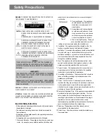


Safety Precautions
WARNING
: TO PREVENT FIRE OR ELECTRIC SHOCK, DO NOT EXPOSE
THIS APPLIANCE TO RAIN OR MOISTURE.
CAUTION :
TO REDUCE THE RISK IF ELECTRIC SHOCK, DO NOT
REMOVE COVER (OR BACK). NO USER SERVICEABLE PARTS
INSIDE.
REFER SERVICING TO QUALIFIED SERVICE PERSONNEL.
THIS SYMBOL IS INTENDED TO ALERT THE USER TO THE
PRESENCE OF UNINSULTED "DANGEROUS VOLTAGE"
WITHIN THE PRODUCT'S ENCLOSURE THAT MAY BE
SUFFICIENT MAGNITUDE TO CONSTITUTE A RISK OF
ELECTRIC SHOCK TO PERSONS.
THIS SYMBOL IS INTENDED TO ALERT THE USER TO THE
PRESENCE OF IMPORTANT OPERATING AND MAINTENANCE
(SERVICING) INSTRUCTIONS IN THE LITERATURE
ACCOMPANYING THE APPLIANCE.
CAUTION
TO PREVENT ELECTRIC SHOCK, DO NOT USE THIS POLARIZED AC
PLUG WITH AN EXTENSION CORD, RECEPTACLE OR OTHER OUTLET
UNLESS THE BLADES CAN BE FULLY INSERTED TO PREVENT BLADE
EXPOSURE.
LASER SAFETY
THIS UNIT EMPLOYS A LASER. ONLY QUALIFIED SERVICE PERSONNEL
SHOULD REMOVE THE COVER OR ATTEMPT TO SERVICE THIS DEVICE
DUE TO POSSIBLE EYE INJURY.
CAUTION :
USE OF ANY CONTROLS, ADJUSTMENTS, OR PROCEDURES
OTHER THAN THOSE SPECIFIED HEREIN MAY RESULT IN HAZARDOUS
RADIATION EXPOSURE.
CAUTION :
TO PREVENT ELECTRIC SHOCK, MATCH WIDE BLADE OF
PLUG TO WIDE SLOT, FULLY INSERT.
ATTENTION :
POUR EVITER LES CHOCS ELECTRIQUES, INTRODUIRE
LA LAME LA PLUS LARGE DE LA FICHE DANS LA BORNE CORRESPON-
DANTE DE LA PRISE ET POUSSER JUSQU'AU FOND.
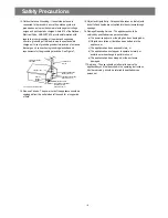
Important Safety Instructions
- All the safety and operating instructions should be read before
the appliance is operated.
- The safety and operating instructions should be retained for
future reference.
- All warnings on the appliance and in the operating instructions
should be adhered to.
- All operating and use instructions should be followed.
1. Water and Moisture - The appliance should not be
used near
water - for example, near a bathtub, washbowl, kitchen sink,
laundry tub, in a wet basement, or near a swimming pool,
and the like.
2. Carts and Stands - The appliance
should be used only with a cart or
stand that is recommended by th
manufacturer.
3. An appliance and cart combination
should
be moved with care.
Quick
stops, excessive force, and uneven
surfaces may cause the appliance
and
cart combination to overturn.
4. Wall or Ceiling Mounting - The appli-
ance
should be mounted to a wall or
ceiling
only as recommended by the
manufacturer.
5. Ventilation - The appliance should be situated so
that its
location or position does not interfere with
its proper
ventilation. For example, the appliance
should not be situated
on a bed, sofa, rug, or
similar surface that may block the
ventilation
openings; or, placed in a built-in installation, such
as a bookcase or cabinet that may impede the flow
of air
through the ventilation openings.
6. Heat - The appliance should be situated away from
heat
sources such as radiators, heat registers,
stoves, or other
appliances (including amplifiers) that
produce heat.
7. Power Sources - The appliance should be
connected to a
power supply only of the type
described in the operating
instructions or as marked
on the appliance.
8. Grounding or Polarization - The precautions that
should be
taken so that the grounding or
polarization means of an
appliance is not defeated.
9. Power - Cord Protection - Power-supply cords
should be
routed so that they are not likely to be
walked on or pinched
by items placed upon or
against them, paying particular
attention to cords at
plugs, convenience receptacles, and the
point where
they exit from the appliance.
10.Protective Attachment Plug - If the appliance is equipped with
an attachment plug having overload
protection. This is a
safety feature.
See Instruction Manual for replacement or
resetting of
protective device. If replacement of the plug is
required, be sure the
service technician has used a
replacement plug
specified by the manufacturer that has the
same overload protection as the original plug.
11.Cleaning - The appliance should be cleaned only as
recommended by the manufacturer.
12.Power Lines - An outdoor antenna should be located
away
from power lines.
CAUTION
RISK OF ELECTRIC SHOCKS
DO NOT OPEN
PORTABLE CART
Figure 2
- 2 -
Summary of Contents for XL-115
Page 1: ...Service Manual MINI COMPONENT SYSTEM Model DAEWOO ELECTRONICS CO LTD XL 115...
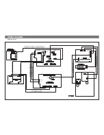
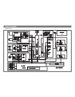
Page 9: ...BLOCK DIAGRAM Model No XL 115 8...
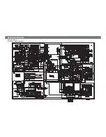
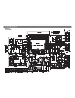
Page 11: ...Schemetic Diagram Model No XL 115 Ass y Name CD 1 0...
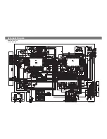
Page 12: ...Schemetic Diagram Model No XL 115 Ass y Name Control 11...
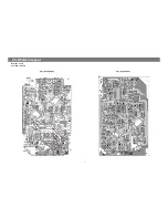
Page 13: ...P C B Pattern Layout 12 Model No XL 115 Ass y Name MAIN PCB...
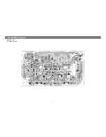
Page 14: ...Model No XL 115 Ass y Name CD P C B P C B Pattern Layout 13...
Page 15: ...Model No XL 115 Ass y Name Front PCB 14 P C B Pattern Layout...
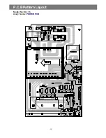
Page 16: ...P C B Pattern Layout Model No XL 115 Ass y Name POWER PCB 15...