background image

21

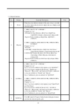
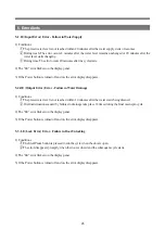
2-2. Rinse Cycle

1) Drainage


1

 If the water is 55°C or hotter, cold water is added to lower the water temperature. When the water 

temperature decreases to 50°C or lower, water drainage resumes.


2

 After the water drainage starts, the drain pump continues to work.


3

 If the water level lowers to the reset level within 60 seconds, the waiting time of 20 seconds applies. 

Otherwise, the waiting time of 40 seconds applies.

2) Intermediate Spin


1

 Intermediate spin is run at the pre-determined speed for each program.

3) Water Supply


1

 Only cold water is supplied to the rinse cycle.


2

 Fabric softener is added to the final rinse cycle.

4) Resupply of Water


1

 The water level is measured a minute after the rinse cycle starts to determine whether water needs to be 

added to raise the water level to the preset level.

2-3.Spin Cycle

1) Drainage


1

 It is equivalent to the drainage cycle for rinsing.

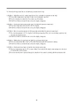
2-3.Spin Cycle

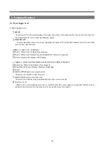
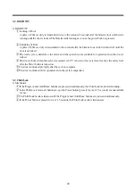
1) Termination of Door Lock


1

 After the electric signal to door lock is cut off, the door is shaken horizontally until it becomes mechanically 

openable.


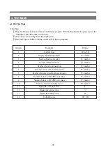
MINI 1.0: D-CV701*, WFWM11* 

MINI 1.5: ODW30-999B, ODW30-999G, DWM30-999PG, WFWM12*

Category

Program

RPM

Normal

700

Delicate

400

Baby Care

700

Night Time

500

QUICK15

700

INTENSIVE(40,60)

700

Category

Program

RPM

Normal

700

Delicate

400

Baby Care

700

Speed up

700

Tub Clean

700

Summary of Contents for MINI 1.0

Page 1: ...l Mounted Front Load Washer MINI S M No WFWM1_1701 In this Manual some parts can be changed for improving their performance without notice in the parts list So if you need the latest parts information please refer to PPL Parts Price List in Service Information Center http webportal dwe co kr sic ...

Page 2: ...Contents 1 What is Wall Mounted Front Load Washer MINI 2 2 Specifications 4 3 Assembly Part List 5 4 PCB Functions 16 5 Wiring Diagram 30 6 Part List and Major Specifications 32 7 Installation 49 ...

Page 3: ...prevents vibrations to ensure silent washing Containers for detergent and softener are discretely designed to prevent mixture The spoon shaped design enables you to apply the proper amount of detergent conveniently Star Drum Star shaped concave convex drum prevents damage to fabric to keep clothes fresh Transparent Door Transparent door allows you to view the contents and check laundry process D C...

Page 4: ...home environment 2 29 Minute Wash As the Normal cycle takes only 29 minutes it speeds up the laundry process and reduces water and power consumption by 64 compared to regular front load washers 3 Baby Clothes Cleaning Mini s Baby Care cycle enables a complete steam wash and rinse function to protect sensitive baby skin from irritation 4 Delicate Cleaning for High Quality Clothes Mini enables daily...

Page 5: ... 302mm mini 1 5 Weight 16 5KG Standard Volume 28L mini 1 0 33L mini 1 5 Power 220V 50Hz CHINA Power Consumption Wash 100W D CV701PC 701AW 701AW 01 Heating 220 240V 1300W mini 1 5 1500W mini 1 0 Max Load Wash 2 5KG Spin 2 5KG Washer Type Front Load Installation Mounted on Wall Water Pressure 0 8 8 0 kgf cm 2 2 1 1 3 3 5 5 4 4 6 NO Parts 1 TUB REAR 2 BODY 3 PROTECTOR GLASS AS 4 DOOR AS 5 COVER BODY ...

Page 6: ...5 3 Assembly Part List 1 TUB AS A13 A01 A02 A03 A04 A11 A09 A12 A22 A23 A24 A25 A26 A29 A28 A27 A30 A31 A20 A19 A21 A18 A17 A07 A16 A10 A14 A15 A08 A06 A05 ...

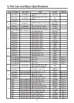
Page 7: ...000 UNITMOTORBLDCDWD200BL NEWMOTECH DC310V 125W CL FEARTH T X 1 Y 36189L8500 UNITMOTORBLDCGJ 2BA003A GNJ DC310V 125W CL F EARTHT X 1 Y 66182 0012500 UNITMOTORBLDCPM92 20 TONLON DC310V 125W CL FEARTH T X 1 Y A18 SPECIALBOLT 3616067010 SPECIALBOLTT S 3 F L5 16 SEALLOCK STS430 4 Y A19 SPECIALSCREW 7S422X4081 TT3 TRS 4X8 SE MFZN 2 Y A20 BRACKET BODY 3610603500 SBHG1 T1 2 1 Y A21 REATOR 3615800500 RT 0...

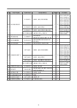
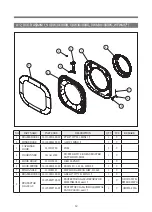
Page 8: ...CLAMPGASKETAS D M300 D1 4 1 Y B02 GAKSET 3612328000 GASKET DOOR D M300 EPDM 1 Y B03 PACKING DETERGENT PRPKCA3R90 PACKINGDETERGENTD M300 SILICONE 2 Y B04 COVER TUB 3618831700 COVER TUB D M300 FRPP 1 Y B05 SCREWTAPPING 90007 0002801 00 MFZN F LT S 2 5 25 H 13 Y B06 GASKETTUB 3612326100 GASKETTUBD M300 PI 4 5 EPDML 1385 1 Y ...

Page 9: ...8 3 COVER BODY AS C01 C05 C08 C06 C02 C03 C04 C07 ...

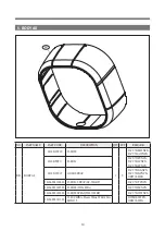
Page 10: ... GY 349A NEW 1 Y D CV701TCNCX ODW30 999B DWM30 999PG 36125 0003006 00 D M300 FRPP BE 3502A NEW 1 Y D CV701GGNCX D CV701GCNCX C04 CAPSCREW 3610917731 CAPSCREWD M300 ABS SPRAY 1 Y 3610917732 CAPSCREWD M300 ABS SPRAYFOR GOLD 1 Y D CV701GGNCX D CV701GCNCX 36109 0002309 00 D M300 ABS WH 011A SPRAY 1 Y D CV701 CHINA ODW JDM883 D CV701WWNCX 36109 0002311 00 ABS WH1404A MINI 1 5 1 Y MINI 1 5 CHINA DWM30 9...

Page 11: ...10 4 1 DOOR AS MINI 1 0 D CV701 WFWM11 ...

Page 12: ...M300 SUS304 D1 6 L36 6 1 Y D04 HOOK DOOR 3613102000 HOOK DOOR D M300 ZNDC 1 Y D05 FRAME DOOR O 36117AE101 D M301 ABS CR GRLDING 1 Y D CV701PCNCX D CV701JCNCX D CV701GCNCX D CV701SCNCX D CV701TCNCX D CV701PCNCX 36117AE102 D M301 ABS SPRAY D CV701MWNCX D CV701AWNCX 36117AE103 D M301 ABS SPRAYFOR GOLD D CV701GGNCX 36121 0005304 00 ABS BG 2501A D M300 D CV701 CHINA ODW JDM883 D06 PROTECTOR GLASS 36183...

Page 13: ...Y 4 DOOR INNER 361A114500 TR PETG HT91 SK GRAY MASTER BATCH DWD M300 1 Y 5 HOOK DOOR 3613102000 D M300 ZNDC 1 Y 6 HOOK SPRING 36130 0001801 00 SUS304 D1 4 L36 6 D M300 1 Y 7 PIN HANDLE 3618200201 SWCH1018A HEAT GILT D3 L48 1 Y 8 FRAME DOOR O 36121 0021300 01 ABS 419 397 26 1 MINI 1 5 1 Y 9 PROTECTOR GLASSAS 36185 0005700 00 PROTECTOR GLASS DECORATOR FILM INMOLD mini 1 5 1 Y ODW30 999B DWM30 999PG ...

Page 14: ... D M301 D CV701PCNCX D CV701JCNCX D CV701PCNCX 361081WF12 GOLD SPRAY D CV701GGNCX D CV701GCNCX ODW30 999B 36104 0001806 00 D M301 SPRAY GY 7801BP D CV701TCNCX 36104 0001807 00 D M300 WH 1802A D CV701SCNCX 36104 0001809 00 D M300 SPRAY WH 1208BP D CV701WWNCX 36104 0001811 00 220V CHINA Cream White WH 1404A MINI 1 5 DWM30 999PG ODW30 999G ...

Page 15: ...512800 ELBOWUNION D M300 AEU0404W1 4 DMT 3 Y F09 CUSHION PAD 3611535360 CUSHION PAD D M300 EPDM 3TID 10 OD 70 4 Y F10 SCREWTAPPING 7115401629 SCREWTAPPINGT1 FLT4X16 SUS 4 Y F11 MANUALOWNERS 36136 0001014 00 SPEEDWASH 1 color printWFWM111 NN00BCCX 1 Y D CV701SCNCX D CV701GCNCX D CV701SCNCX D CV701TCNCX D CV701WWNCX 36136 0001015 00 MINI CHINA DEAC 1 color print XQG30 88 E D CV701MWNCX D CV701JCNCX ...

Page 16: ...6 G04 CONNECTOR 3612512810 UNION CONNECTOR D M300 AUC0404W1 4 DMT 1 Y G05 HOSE INLETAS 3613278000 ADAPTER INLETVALVEAS D M300 HOOKTYPE 1 Y 3613279000 ADAPTER INLETVALVEAS D M300 SCREWTYPE G06 MANUALGUIDE 3612513000 INSTALLGUIDE D M300 1 Y G07 SPECIALBOLTAS 3616067100 ANCHORBOLTAS3 8 M10 SAE1008B L 6 BASIC P W2T30MM 4 Y G08 SPECIALBOLTAS 361A2 0000100 00 3 8 M10 SUS L 8 OPTION P W2T30MM LOCKNUT 4 Y...

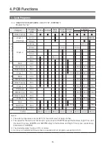
Page 17: ... min 32 min 90 min 40 min 15 min 50 min 80 min 365 min NOTE 1 The water temperature is set at 90 C for the steam wash of baby clothes 2 The speed for the main and interim spin cycles is set at 700RPM except the Delicate Night Time and Intensive 60 cycles 400RPM and 500RPM apply to the Delicate and Night Time cycles respectively Intensive 60 500RPM 3 The drainable water must be 45 C or colder 4 As ...

Page 18: ...set at 700RPM except the Delicate 400RPM and 500RPM apply to the Delicate and Night Time cycles respectively 3 The drainable water must be 50 C or colder 4 As many as 5 additional rinse cycles are available for all programs except Speed Wash cycles 1 1 2 SEQUENCE CHART MINI 1 5 ODW30 999B ODW30 999G DWM30 999PG WFWM12 Program Ver u1 ...

Page 19: ...sive40 Intensive60 Regular Normal Delicate Tub Clean Spin Speed Wash Intensive 3 Add Rinse 1 MINI 1 0 D CV701 WFWM11 Program Ver q1 Up to 5 cycles are addable for all program except QUICK15 Up to 8 cycles are available for Baby Care Night Time Intensive INtensive40 and Intensive60 while 7 additional cycles are available for Normal and Deicate Up to 5 additional cycles are availavle for QUICK15 2 M...

Page 20: ...evel after the additional cycle the heating cycle is suspended and the main wash cycle starts 3 The water heater does not resume its operation after it is turned off when the water temperature reaches the target level 1 MINI 1 0 D CV701 WFWM11 2 MINI 1 5 ODW30 999B ODW30 999G DWM30 999PG WFWM12 2 Program Functions Category Program Water level Time of water supply Heating time Wash time Total wash ...

Page 21: ...ed every two minutes after the initial water supply to drain water if the level is above the overflow level 2 If the water level is measured above the overflow level three times the E3 error is displayed and the wash cycle is suspended However the water continues to be drained 3 If the water level is first measured to be above the overflow level during the Baby Care program the heating cycle is sk...

Page 22: ...he rinse cycle 2 Fabric softener is added to the final rinse cycle 4 Resupply of Water 1 The water level is measured a minute after the rinse cycle starts to determine whether water needs to be added to raise the water level to the preset level 2 3 Spin Cycle 1 Drainage 1 It is equivalent to the drainage cycle for rinsing 2 3 Spin Cycle 1 Termination of Door Lock 1After the electric signal to door...

Page 23: ...ogram 5 Wash 3 Intensive40 Intensive60 Program 2 MINI 1 5 ODW30 999B ODW30 999G DWM30 999PG WFWM12 3 Wash Low Water level for Baby Care program 4 Wash Mid Water level Normal Delicate Night time 5 Wash 3 6 LOCK OFF Water level to unlock door Water level to enable to open the door 7 LOCK ON Water level to lock door Water level to lock the door automatically due to the water in the tub 8 Overflow Lev...

Page 24: ...ked 4 The door is locked when the water is measured at 61 C or hotter or the water level is above the safety level after the Power button is turned on 5 The door is unlocked promptly after the cycle is complete 6 The door is unlocked if it is openable when the cycle is suspended 3 3 Child Lock 1 Mechanism 1 If the Program and Add Rinse buttons are pressed simultaneously the Child Lock mode starts ...

Page 25: ...oor LC or LO 2 Display the durability number rn number 3 Number of hall sensor errors b1 number 4 Number of IPM fault errors b2 number 5 Number of motor overload errors b3 number 6 Number of errors in motor arrangement b4 number 7 Number of failures in tracking the motor speed b5 number 8 Number of errors in DC LINK overvoltage b6 number 9 Number of errors in DC LINK low voltage b7 number 10 Numbe...

Page 26: ...lure in Water Drainage 1 Conditions 1 The preset water level is not reached within 10 minutes after the water starts being drained 2 Overload situations caused by failures in drainage take place 18 times during the final main spin cycle 2 The LE error flickers on the display panel 3 If the Power button is turned off and on the error display disappears 5 3 LE Lock Error Error Failure in Door Unlock...

Page 27: ...d but water continues to be drained 2 If the water level is first measured to be above the overflow level during the Baby Care program the heating cycle is skipped The E3 error is displayed on the third occurrence of overflow detection and the wash cycle is subsequently suspended However the water continues to be drained 2 The drainage synchronous motor continues to work until the water level drop...

Page 28: ... error display disappears 3 b3 Error Motor overload error 4 b4 Error Failure in motor arrangement 5 b5 Error Failure in tracking the motor speed 6 b6 Error Error in DC LINK overvoltage 7 b7 Error Error in DC LINK low voltage 8 b8 Error Failure in starting motor 1 The error is caused by failure to rotate the motor due to the initial overrunning of motor 2 The motor stops running and 30 retrials are...

Page 29: ...for Delicate program Available for premium model only 1 The water temperature is 45 C or higher in the Delicate program The error occurs during operation only when the tub contains water 2 If the Power button is turned off and on the error display disappears 4 H6 Error Malfunction of water heater Available for premium model only 1 The water temperature fails to rise by 2 C within 30 minutes after ...

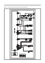
Page 30: ...V 4 DRAIN PUMP 5 DRAIN CHECK 6 LOCK CHECK 7 DETERGENT PUMP 8 RINSE PUMP 9 DRY V V 10 DOOR LOCK 1 2 3 4 5 6 7 1 MINI 1 0 D CV701 WFWM11 2 MINI 1 5 ODW30 999B ODW30 999G DWM30 999PG WFWM12 N303 BLUE 3PIN 1 DRY_HEATER_RELAY 2 WASH_HEATER_RELAY 3 AC1 LIVE N201 WHITE 3PIN 1 W 2 V 3 U N101 WHITE 2PIN 1 無 2 AC1 LIVE N501 WHITE 7 PIN 1 RESET 2 RX_FROM_FRONT 3 TX_TO_FRONT 4 POWER KEY 5 5V 6 GND 7 15V N502 ...

Page 31: ...30 5 Wiring Diagram D CV701 01 D CV701 ...

Page 32: ...31 MINI 1 5 ODW30 999B ODW30 999G DWM30 999PG WFWM12 ...

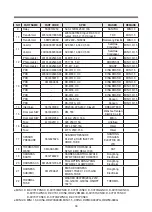
Page 33: ...Seshin 6 Fuse M PCB 40504 0002700 00 250 V 8 A ORISEL MINI 1 5 Fuse M PCB 250 V 6 3 A ORISEL MINI 1 5 Fuse M PCB 40504 0002700 00 250 V 8 A Littel Fuse MINI 1 5 Fuse M PCB 250 V 6 3 A Littel Fuse MINI 1 5 7 EMI FILTER 3611913100 EMI FILTER RDFC 2720 MINI DRUM 250V 12A BRAKET Ruikai EMI FILTER LFT 215W 250 V 12 A SangShin Electronics 8 X Capacitor 40C01 0014300 00 PCX2 335M 275 V 0 1 µF Pilkor MINI...

Page 34: ... DS 7405 V 0 Doosan MINI 1 0 1 5 PCB DS 1107A V 0 Doosan MINI 1 0 1 5 14 Inlet Valve 3615401000 DR23AS 220 240 V Class B DREAM TECH 15 Door Lock S W 3619047230 DM T85 Wenzhou Tianjian Electric Co Ltd Door Lock S W 3619047250 DL S2 250 V 16 A Bitron 16 Fuse 4414A25110 326 250V 15A Littelfuse Fuse 65TL 250V 15A Orisel Fuse 61TS 250V 15A Orisel 17 SENSOR PRESSURE 361482532A SENSOR PRESSURE DL DW12 H ...

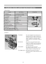
Page 35: ...ransform the electric energy from stator into mechanical energy It consists of the shaft and pulley to transmit the mechanical energy to outside Belt is fixed on the pulley to enable set rotation 2 STATOR The stator has a magnetic function which requires coil winding for electric transmission to produce iron cores and electromagnets for magnetic functionality 3 MAGNET The magnet transmits energy a...

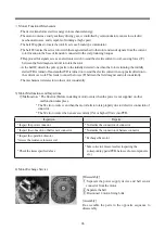
Page 36: ...assemble the parts in the opposite sequence to disassembly Motor s Functional Mechanism The device transforms electric energy into mechanical energy The motor contains a costly auxiliary driving gear is controlled by semiconductors causes low electric mechanical noises and is capable of running at high speed The hall IC applies to locate the rotor It acts as a brush type commutator The hall IC loc...

Page 37: ...Operation Valve Operation Location of Cam Description The bellows are completely closed the location of cam is set at 0 degree and the connection is off The wash cycle does not start yet After the power supply is connected the synchronous motor starts operating and the cam begins to rotate at the same time to open the bellows Location of cam is set at 90 degrees and the connection is on After the ...

Page 38: ...nternal switch is off signals continue to be transmitted to the drain motor until the internal switch is turned on If the internal switch is turned on signals are sent to the drain motor for about 3 6 seconds which is subsequently turned off When the drainage valve is off When the internal switch is on signals continue to be transmitted to the drain motor until the internal switch is turned off If...

Page 39: ...ge only the motor if the motor causes poor operation Assembly Re assemble the parts in the opposite sequence to disassembly STOPPER BASE MOTOR Drain Motor bellows Assembly 4 In the event of OE after remdy follow the below directions Inspection method Remove the join area around 100mm from the hose drain After removal clean the area where the foreign object was located HOSE DRAIN O 100mm Clean the ...

Page 40: ...0 C DiaphragmOpreation 2 0mm or more 1 Specification 2 Operation If the power supply is connected to the water inlet valve the rod valve is drawn by the coil s magnetic field to open the diaphragm hall and push up the diaphragm with water pressure This leads to open the water flow and start the water supply If the power supply is cut off the coil s magnetic field disappears and the force of intern...

Page 41: ...es Inspect any openings and blockages in pressure hoses Exchange the defective part E2 Defective valve Check the malfunctions in valve Exchangetheinletvalve Others Check any leaks from the sides of inlet valve Check any leaks from the sides of inlet valve Exchange the inlet valve Unavailable water supply PCB 1 Inspect the insertion of PCB pin Easily detachable if the wire is pulled Housing on pin ...

Page 42: ... fit on inlet red pressed separate the inlet hose With the snap fit on outlet gray pressed separate the inlet hose 4 Unscrew a bolt Notes 1 Connect the inlet hose properly to the inlet red and outlet gray 2 Fasten the screw properly to prevent abrasion 3 Insert the inlet hose into valve tightly Assembly of Inlet Valve ...

Page 43: ... temperature fuse is designed to be cut off about a minute after overheating to prevent such problems The heater temperature is set at around 270 C The water heater must be used in water Water Heater Water Temperature Sensor Category Specifications Note Maker 1RCA Voltage 220V Power Consumption 1400 W 5 Resistance 34 570hm Current Desnity 11 9 Temperature Fuse 184 C Thermister Included in heater M...

Page 44: ...f sensor See the attached Water Resistance Table Exchange the temperature sensor H2 or H4 Exchange of Heater Exchange of Water Heater Disassembly 1 Remove 4 body fixing screws 2 Remove the detergent and softener containers 3 Remove 2 screws fixing the door hinge 4 Remove 6 cover screws fixing the cover tub 5 Remove 6 screws fixing the cover tub 6 Remove the connector of water heater 7 Remove the n...

Page 45: ... transformed into digital signals and transmit a square wave to display the oscillation cycle in a frequency format The frequency signals predetermined in the set play switching functions to control the head pressure in the tub After the wash cycle is complete at the preset level and the water is drained the head pressure declines to return the metal core to the original condition enabling the rep...

Page 46: ...l The reset level is immeasurable Defects and Errors Details Causes Inspection of Defects and Errors Resolution PCB Error Mode Incessant water supply Water continues to be supplied although the inlet valve is functioning well Defect in the bellows of water level sensor Check the frequency Exchange the water level sensor E2 Defect in pressure sensor hoses Check the frequency Exchange the hose E2 In...

Page 47: ...licable to DE type only 1 LE error occurs without any snapping sounds in DF type 2 LE error occurs in DA type Disconnected connector Inspect the connection of connector with naked eyes Insert connector LE Terminal disconnected from connector See the disassembly and inspection manual for door lock switch below Insert terminal S W No 4 or 5 terminal LE Door poorly closed Close the door completely LE...

Page 48: ...d Errors Resolution Error Mode Non openable Door Power cutoff or forced shutdown during operation After the power cutoff or forced shutdown during operation PCB MICOM is not able to open the door At least 5 minutes must pass before the door becomes openable The washer is ON without any power cutoffs Water in tub Check whether the water level is above the safety level High temperature in tub The do...

Page 49: ...WELL WHITE 3X1 5SQ 250V 15A LONGWELL AUSTRALIA 3 EU 3611339660 3611339680 3611339670 3611339690 HONGCHANG DTIII 2P 05 250V 16A H05VV F 3X1 5 EURO 4 Chile 3611342840 3611342860 3611342850 3611342870 HONGCHANG DTIII 3P 01 250V 10A H05VV F 3X1 5 CHILE 5 U K UAE 3611342900 3611342920 3611342910 3611342930 LONGWELL LP 61L H05VV F 3X1 5SQ 250V 13A IMPORT UK 6 CHINA 3611342700 3611342720 3611342710 36113...

Page 50: ...ightbelowafaucet UseTE2 SSoftHammerdrillfromHILTIoraDrill 4 1 Drill a hole into the tile Insertsetanchorsintotheholes Setanchorsareincludedintheproduct packaging Insertsetanchorsintotheendofeachhole thesetanchorboltpartsmustbe75mmorlonger abovethewall 5 Insert set anchors 4 units Setthehammerdrilloradrillperpendiculartothe surfaceofthewallanddrillaholeintothe retainingwall Followtheinstructionsont...

Page 51: ...enutmaycausedamageto thewashingmachineorthewalltile Fixingnutmustbefastenedtotheend 12 Fix the washing machine Closethewatersupplyvalve Disassemblethewatersupplyvalve Installthebranchingadapter Branchofftheinlethose WraptheconnectionofthebranchingadapterandwatersupplyvalvewithTeflontape Checkleakageafterinstallation 13 1 Install the inlet hose Regular faucet Installthewatertapconnectoron thefaucet...

Page 52: ... mountingthebody Checkifthereisanyspaceoneitherside 16 Mount the Body The washing machine is recommended to be installed by a professional service engineer Follow the table below when drilling the tiles with tools Note Wall type Depth of Hole Bit diameter of hammer drill Bit diameter of tile hole Cement wall 45mm ø 14mm Concrete wall 45mm ø 14mm Tiled wall The distance between the actuall wall and...

Page 53: ...thclampwhenconnected upward Fixthegroundingcableswithflatscrews Donotusemultiplegroundingcablesinonespot 8 Plug the power cord Inserttheinlethoseuntiltheelbowmakesasnapping sound Fixthedrainhosetothesynchronousmotorand connecttheclampinsidethesynchronousmotor Connecthosesproperlytopreventanyleakage Insertinletanddrainhosesintothebackholesafter connection 7 Connect inlet and drain hoses Makeanotchu...

Page 54: ...on Fixtheitemsasfollows Rubberpad 1ea Plain washer 1ea Springwasher 1ea Nut 1ea Springwasher 1ea nut 1ea Fastenthenutwithaspanner Excessivefasteningofthenutmaycausedamageto thewashingmachineorthewalltile Fixingnutmustbefastenedtotheend 12 Fix the washing machine Closethewatersupplyvalve Disassemblethewatersupplyvalve Installthebranchingadapter Branchofftheinlethose Wraptheconnectionofthebranchinga...

Page 55: ...Connect4upperandlowerboltsaftermountingthebody Checkifthereisanyspaceoneitherside 16 Mount the Body The washing machine is recommended to be installed by a professional service engineer Follow the table below when drilling the tiles with tools Note Wall type Depth of Hole Bit diameter of hammer drill Bit diameter of tile hole Hollow wall Tile 100mm ø 14mm ø 16mm perforated wall Concrete wall ...

Page 56: ...ter pipes are plastic pipes If the power cord is damaged contact a nearby service center or the sales store as special tools are required Exchange power cord Contact a nearby service center to relocate the washing machine Additional charges apply Relocation 7 3 WHEN IT CANNOT BE INSTALLED ACCORDING TO THE TWO INSTRUCTIONS ABOVE Setthehammerdrilloradrillperpendicular tothesurfaceofthewallanddrillah...

Page 57: ......

Page 58: ... Service Manual 접 수 2017 02 02 M E M O 총 57p 17 02 02 표지 4p 5p 6p 8p 10p 13p _ 7p 17 02 13 1p 4p 5p 6p 7p 8p 9p 페이지 추가 _ 7p 17 02 14 15p 54p 55p 페이지 추가 _ 3p 권종하 님 17 02 16 11p 12p 13p 14p 15p 55p _ 6p 김현규 님 17 02 17 6p 15p 32p 33p 55p _ 5p ABOUT THIS MANUAL 주 신광씨링 광주광역시 서구 하남대로 502번길 14 NO NEED PRINT ...

Reviews: