background image

English - 3

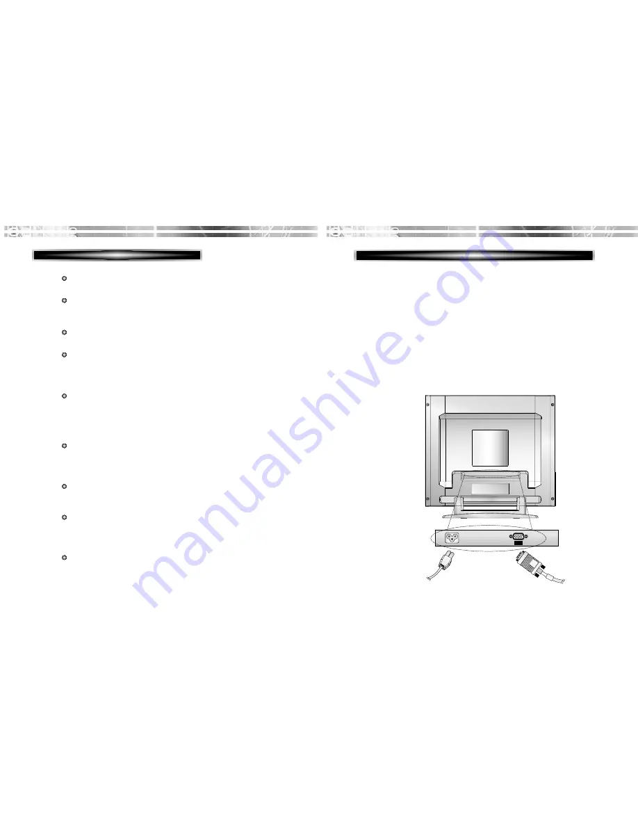
1. Turn off the computer and monitor.

2. Connect the 15 pin signal cable to the output port of the video

card in your computer and monitor.

3. Tighten the screws of the 15 pin signal cable.

4. Plug the power cord into the AC receptacle located on the back

of the monitor. 

5. Plug the other end of the power cord into the AC outlet.

SETUP

SETUP

CONNECTING THE 15 PIN SIGNAL CABLE AND POWER CORD

English - 2

PRODUCT FEATURES

AC  POWER

The monitor is designed for use in a small work area or for
those who need more work space on the desk.

The convenient and user-friendly on-screen display allows for
easy and accurate adjustments of screen size, position and
screen color.  

The monitor supports a safe working environment in strict
compliance with the TCO 99 standard for low emissions .

The monitor complies with the VESA Display Data Channel
(DDC) specification for Plug and Play compatibility.
Advanced microcircuitry makes setup and configuration fast
and effortless.

The monitor features Advanced Color Controls for fine-tuning
to meet your own personal tastes or application requirements.
Use the on-screen controls to adjust the color temperature,
RGB gain value for the best possible screen color and
intensity.  

Press the menu button and activate the Self-Diagnosis menu to
determine whether your monitor is functioning normally, not
receiving a signal or is receiving a signal that is out of
scanning range.

Activate the higher refresh rates of the monitor to stabilize the
screen and eliminate the annoying flicker that contributes to
eye-strain and headaches.

The “borderless” full-screen display capability works under all
graphic modes and provides a larger viewing area than
conventional monitors, giving you a better picture with more
workspace.

The monitor supports the optimal display performance with
1280x1024 at 60Hz. 

Power

Cord

15 pin

signal

cable

Summary of Contents for L700C

Page 1: ...http www dwe co kr TFT LCD MONITOR Model No L700C USER S GUIDE...

Page 2: ...em ISO 7779 FEDERAL COMMUNICATIONS COMMISSION RADIO FREQUENCY INTERFERENCE STATEMENT NOTE This equipment has been tested and found to comply with the limits for a Class B digital device pursuant to Pa...

Page 3: ...Signature J K Choi Director Display Business Division DAEWOO ELECTRONICS CO LTD Emission Characteristics Tested by SEMKO A sample of this type has been tested and has shown compliance with theguideli...

Page 4: ...best performance from your monitor Please read this user s guide carefully before installing your monitor then keep it near your monitor for quick reference First please check that the contents of th...

Page 5: ...ata Channel DDC specification for Plug and Play compatibility Advanced microcircuitry makes setup and configuration fast and effortless The monitor features Advanced Color Controls for fine tuning to...

Page 6: ...ected function moves cursor to the left or high window in the OSD window and decreases value of any selected function moves from top menu to sub menu in the OSD window and opens the function window fo...

Page 7: ...ng the illuminated pixels and adjust until the screen image looks focused crisp and sharp Adjusting the CLOCK FINE after the CLOCK adjustment will produce a clear screen Adjust the red color Adjust th...

Page 8: ...when the applied frequency is under or over normal range Normal range Non interlaced mode only H 30 80 KHz V 56 77 Hz None support screen is displayed when the applied frequency is under or over facto...

Page 9: ...contrast ratio typ Brightness 250cd m2 brightness typ Color Filter RGB vertical stripe Synchronization Horizontal 30 80KHz Vertical 56 77Hz Video Bandwidth 135MHz Max Resolution 1280 x 1024 75Hz Color...

Page 10: ...on interlaced XGA 1024 X 768 75Hz 60 0 75 Non interlaced SXGA 1280 X1024 60Hz 64 0 60 Non interlaced SXGA 1280 X1024 75Hz 80 0 75 Non interlaced SXGA 1152 X 864 75Hz 67 5 75 Non interlaced SXGA 1280 X...

Page 11: ...e power cord is correctly connected Check if the signal cable is suitable to the video card Adjust Clock or H V Center to get the proper image Keep the devices that may cause electrical interference a...

Page 12: ...4 5 6 7 8 9 10 11 12 13 14 15 Signal Red Green Blue GND GND GND Red GND Green GND Blue 5Vdc GND H Sync GND V Sync Bi directional Data SDA Horizontal Sync Vertical Sync VCLK Data Clock SCL 1 6 15 10 G...

Reviews: