35
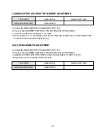
J. AUDIO OUTPUT (A/C HEAD TILT & HEIGHT ADJUSTMENT)
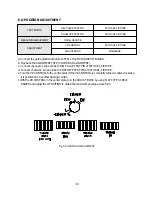
a. Connect the OSCILLOSCOPE to the AUDIO OUTPUT JACK.
b. Play back the ALIGNMENT TAPE (NTSC: DN1 (SP, 1KHz), PAL: DP1 (SP, 1KHz)).
c. Check the AUDIO OUTPUT SIGNAL is -9~-3dBm.
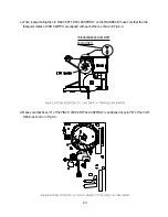
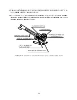
d. If the requirement "c" is not satisfied, adjust the A/C HEAD TILT SCREW and A/C HEAD HEIGHT NUT
to obtain the maximum audio output. (Fig. 5-3)
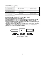
K. A/C HEAD AZIMUTH ADJUSTMENT
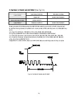
a. Connect the OSCILLOSCOPE to the AUDIO OUTPUT JACK.
b. Play back the ALIGNMENT TAPE (NTSC: DN2 (SP, 7KHz), PAL: DP2 (SP, 6KHz)).
c. Adjust the A/C HEAD AZIMUTH SCREW to obtain the audio output -9~-3dBm. (Fig. 5-3)
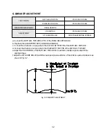
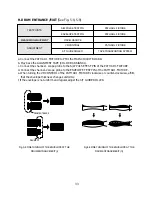
d. Repeat the process "H. DRUM ENTRANCE/EXIT".
TEST POINTS
AUDIO OUTPUT
AUDIO OUTPUT JACK
MEASURING EQUIPMENT
OSCILLOSCOPE
TEST POINTS
AUDIO OUTPUT
AUDIO OUTPUT JACK
MEASURING EQUIPMENT
OSCILLOSCOPE
Summary of Contents for K30
Page 4: ...3 1 2 1 WIRE DIAGRAM 1 2WIREDIAGRAM ...
Page 8: ...7 2 1 2 PARTS LOCATION OF FRONT LOADING ASS Y A TOP VIEW B FRONT VIEW ...
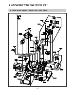
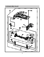
Page 38: ...37 6 EXPLODED VIEW AND PARTS LIST 6 1 EXPLODED VIEW OF DECK ASS Y TOP VIEW ...
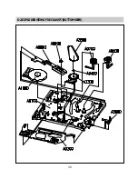
Page 39: ...38 6 2 EXPLODEDVIEWOFDECKASS Y BOTTOMVIEW ...
Page 40: ...39 6 3 EXPLODEDVIEWOFF LASS Y ...
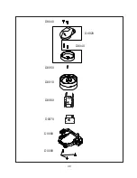
Page 41: ...40 D0040 D0020 D0050 D0010 D0080 D0090 D0060 D0070 D0040 ...

