20
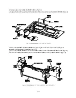
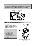
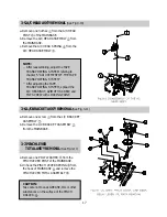
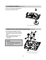
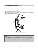
3-11. CAPSTAN MOTOR REMOVAL
(See Fig.3-18)
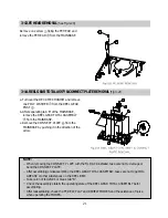
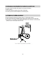
3-12. IDLER PLATE TOTAL ASS'Y & S/T REEL TABLE REMOVAL
(See Fig.3-19)
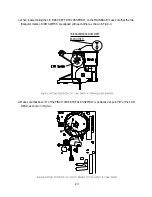
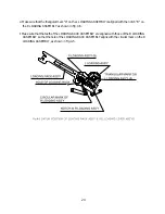
Remove 3 screws fixing the CAPSTAN MOTOR
and separate the CAPSTAN MOTOR.
a. Remove one POLY WASHER
from the
REEL GEAR POST
and remove the IDLER
PLATE TOTAL ASSEMBLY
from the MAIN
BASE.
b. Remove the S/T REEL TABLES
and two
POLY SLIDERS
from the DECK
MECHANISM.
CAUTION:
When disassembling or assembling the
IDLER PLATE TOTAL ASSEMBLY, take
care not to bend it.
Summary of Contents for K30
Page 4: ...3 1 2 1 WIRE DIAGRAM 1 2WIREDIAGRAM ...
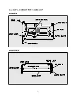
Page 8: ...7 2 1 2 PARTS LOCATION OF FRONT LOADING ASS Y A TOP VIEW B FRONT VIEW ...
Page 38: ...37 6 EXPLODED VIEW AND PARTS LIST 6 1 EXPLODED VIEW OF DECK ASS Y TOP VIEW ...
Page 39: ...38 6 2 EXPLODEDVIEWOFDECKASS Y BOTTOMVIEW ...
Page 40: ...39 6 3 EXPLODEDVIEWOFF LASS Y ...
Page 41: ...40 D0040 D0020 D0050 D0010 D0080 D0090 D0060 D0070 D0040 ...

