background image

29

Time Lapse Video Cassette Recorder

28

Time Lapse Video Cassette Recorder

Recording Check

During recording, press the REC CHECK button.

• The tape will be rewound for about 5 seconds and  slow

play mode will be performed. The VCR will then return
to the previous recording mode.
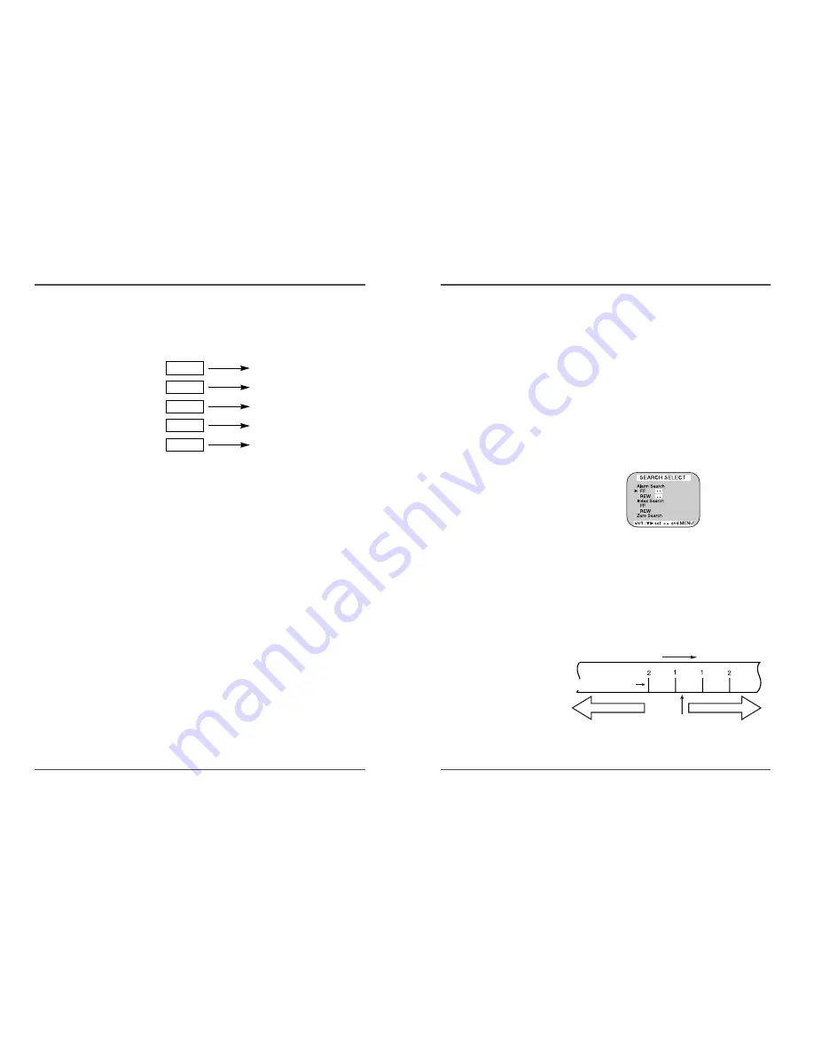
Alarm Search

1

Press the Menu button to display the initial menu.

2

Press the SHIFT

button to select Search Select,

then press the SHIFT 

button to display the

SEARCH SELECT menu.

3

Move the arrow mark (

) to FF or REW in the

Alarm Search mode as you want to search.

4

Press the SET – (or +) button to enter the number
of alarm marks you want to search, press the SHIFT

√ 

button to search forward or in reverse.

•  The display returns to the normal screen.
•  The VCR will locate the desired alarm recording and

begin playback.

• During recording check

operations, recording is
suspended momentarily.

Reverse Play

•  Press R.PLAY button on remote control in playback

mode to enter into Reverse Play mode.

•  To return to normal playback, press the PLAY button.

Picture Search

1

Press the FF/CUE (or REW/REVIEW) button, during
normal playback.

•  The image can be seen while the tape is advanced (or

rewound) at high speed.

2

To return to normal playback, press the PLAY button.

Still Image

1

Press the PAUSE/STILL button, during normal
playback.

•  A still image can be viewed.

2

To return to normal playback, press the PLAY button.

•  With each press of the PAUSE/STILL button, the still

image is advanced one image (frame).

Vertical Lock Control

During still image mode,
1

Press the TR button to reduce the vertical
rolling of the image.

2

If it cannot be corrected, press the TRACKING – button.

• During picture search,

noise (horizontal bars) will
appear in the picture.

• The sound is muted.

• If still mode continues for

5 minutes or more, the
VCR will go into stop
mode to avoid damaging
the tape.

• If the image is unstable

(rolling vertically), adjust
the tracking control to
correct.

• The tape recorded in 48H

mode will be
reverse–playback in 3H.
And the tape recorded in
18H or 30H mode will be
reverse–playback in 6H.

• During reverse–playback

in 3H and 48H, noise
band may appear in the
picture. And during
reverse–playback in 6H,
noise may appear in
upper or bottom side of
the picture.

Playback

Alarm number

Alarm trigger input point

Rewind direction

Actual position

Fast forward direction

3H Play

3H Reverse Play

R.PLAY button

6H Play

6H Reverse Play

R.PLAY button

18H Play

6H Reverse Play

R.PLAY button

30H Play

6H Reverse Play

R.PLAY button

48H Play

3H Reverse Play

R.PLAY button

Summary of Contents for EV-VCR960

Page 1: ...APSERECORDERWITH40HR REALTIMEREC User s Guide EV VCR960 EJECT REC Be sure to read carefully and follow all the SAFETY INFORMATION on page i Keep the manual in a safe place for future reference P N 97P...

Page 2: ...the power supply and aerial if you will not be using the recorder for a long period or during a thunderstorm For your own safety There are no components in this Time Lapse video cassette recorder you...

Page 3: ...te Control 5 Connections 6 Video Cassettes Tapes 7 Types of On screen displays and Display Sequence 8 Setting the Clock 10 Changing the On Screen Display 12 Normal Recording 14 Program Timer Recording...

Page 4: ...y eg 7 HOUR 07 MINUTE ERROR display eg E Error 04 Error No E 01 The cassette cannot be loaded or unloaded E 02 The tape stops E 03 The drum can not rotate properly E 04 The tape is cut broken E 05 The...

Page 5: ...on 21 REVERSE PLAY button 22 REC button 23 REC PLAY SPEED button 24 REC CHECK button 25 MENU button 4 Time Lapse Video Cassette Recorder Back Panel 1 ALARM 2 ALARM Input terminal 2 ALARM 3 ALARM Input...

Page 6: ...formance Handling Cassette Tapes Cassette tapes should always be stored vertically in their cases away from high temperatures magnetic fields direct sunlight dirt dust and locations subject to mold fo...

Page 7: ...ed and the normal screen is displayed During recording or playback the menus cannot be displayed Press the MENU button First time Press the SHIFT button to move the arrow mark downward for the desired...

Page 8: ...last 2 digits only are displayed The day of the week is set automatically 12 Press the MENU button three times the normal screen is displayed The setting procedure is now complete Setting the Clock Ex...

Page 9: ...is changed identically 9 Press the SET or button to set the position of the counter and title to C Top or R Top or L Top If one of 2 items is set the position of 2 items is changed identically L Top C...

Page 10: ...he display panel and recording starts 5 To stop recording press the STOP button If the Repeat Rec Set is set to NO in the REC MODE SET menu recording will continue to the end of the tape then stop and...

Page 11: ...display panel The VCR is now in timer recording stand by mode If the set stop time is earlier than or the same time as the set start time the VCR will consider the stop time to be the following day P...

Page 12: ...y panel The VCR internal battery is completely charged after the VCR has been connected to an AC power outlet for 48 hours and it will maintain all the VCR settings memory for up to 30 days Set the ti...

Page 13: ...he SHIFT button to display the ALARM REC SET menu 5 Press the SHIFT button to select YES or NO YES The alarm recording takes place when there is alarm trigger input NO The alarm recording does not tak...

Page 14: ...he next only with VCRs of the same model as this one Series Recording Setup 1 Connect 2 VCRs or more as illustrated on next page 2 Set the following items as indicated Item VCR No 1 VCR No 2 and on Ca...

Page 15: ...ton Recording will start When the tape s end is reached the VCR will rewind it to the beginning regardless of the counter memory and recording will resume If during autorepeat recording there is an al...

Page 16: ...op playback press the STOP button To advanced or rewind the tape press the FF CUE or REW REVIEW button Tracking Control 1 While looking at the playback picture press and hold the TRACKING button to mi...

Page 17: ...gh speed 2 To return to normal playback press the PLAY button Still Image 1 Press the PAUSE STILL button during normal playback A still image can be viewed 2 To return to normal playback press the PLA...

Page 18: ...ase indication In 18 hour recording mode each second of the tape counter actually represents approximately 18 6 3 real seconds In the other LP recording speed modes 30H the tape counter indication is...

Page 19: ...e initial MENU 2 Press the SHIFT button to move the arrow mark to SW OUT Terminal Set 3 Press the SHIFT button to display the SW OUT TERMINAL SET menu 4 Press the SHIFT button to set FIELD or FRAME Wi...

Page 20: ...l MENU 2 Press the SHIFT button to move the arrow mark to Alarm Time 3 Press the SHIFT button to display the ALARM TIME menu The number of alarm triggers and the 35 most recent alarm recording times a...

Page 21: ...is terminal is to connect to any external source such as a siren etc 1 High When an alarm input is received and the unit is recording the output becomes DC 5V Once the alarm recording is over the outp...

Page 22: ...er Connecting to a Multiview System for Alarm Recording ALARM 2 ALARM 3 If you are also using a Multi View system use the following diagrams as a guide to connecting the VCR for normal or alarm record...

Page 23: ...he POWER STANDBY ON button Wait for the alarm recording to end Press the STOP button for 3 seconds to stop Wait for the panic recording to end Press the STOP button for 3 seconds to stop Cancel the se...

Page 24: ...larm recording Noise in the playback picture The date and time are not recorded The cassette tape cannot be ejected The unit is not set to timer recording stand by mode N is selected for the TIMER PRO...

Page 25: ...NC 75 unbalanced Audio Input RCA pin jack more than 47k 8 8dBm unbalanced Output RCA pin jack less than 1 5k 7 8dBm unbalanced Microphone input 60 dBs 3 5mm mini jack 10k unbalanced Connectors Alarm i...

Reviews: