background image

1

Time Lapse Video Cassette Recorder

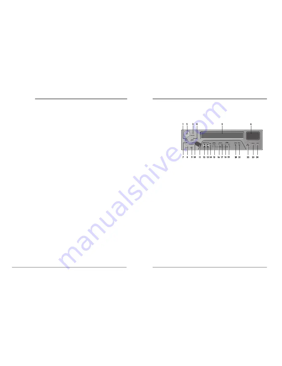
Front Panel

Locations of controls and indicators

1

STOP button

2

REC button

3

REC CHECK button

4

EJECT button

5

CASSETTE LOADING
DOOR

6

DISPLAY PANEL

7

PLAY button

8

REW button

9

FF button

10 PAUSE/STILL button

11 REMOTE SENSOR

12 HIGH PICTURE switch

13 SET LOCK switch

14 RESET button

15 MENU button

16 SHIFT(

) /

TRACKING (–) button

17 SHIFT(

) /

TRACKING (+) button

18 REC/PLAY SPEED(

)

button (SET – button)

19 REC/PLAY SPEED(

)

button (SET +
button)

20 AUDIO ON button

21 DISPLAY button

22 STANDBY/ON button

23 COUNTER button

24 CLEAR button

Time Lapse Video Cassette Recorder

Locations of controls and indicators .............................................................................................. 1

Front Panel .............................................................................................................. 1
Digital Display  ......................................................................................................... 2
Back Panel  .............................................................................................................. 4
Remote Control  ....................................................................................................... 5

Connections ................................................................................................................................. 6
Video Cassettes Tapes .................................................................................................................. 7
Types of On-screen displays and Display Sequence  ...................................................................... 8
Setting the Clock  ........................................................................................................................ 10
Changing the On-Screen Display  ................................................................................................ 12
Normal Recording ...................................................................................................................... 14
Program Timer Recording  .......................................................................................................... 16
Alarm Recording ........................................................................................................................ 20
Panic Recording  ......................................................................................................................... 23
Series Recording  ........................................................................................................................ 23
Autorepeat Recording  ................................................................................................................ 25
Normal Playback ....................................................................................................................... 26

Normal Playback  ................................................................................................... 26
Tracking Control / Vertical Lock Control ............................................................... 26
Audio Playback ...................................................................................................... 27

Special Playback ........................................................................................................................ 28

Digital Shuttle  .........................................................................................................28
Reverse Play / Picture Search  .................................................................................29
Still Image   ............................................................................................................ 29
Recording Check / Alarm Search ........................................................................... 30
Alarm Scan / Index Search  .................................................................................... 31

Other Functions .......................................................................................................................... 32

Tape counter (Zero Search) .................................................................................. 32
Setting the Security Lock (Set Lock) ...................................................................... 33
Setting the HIGH PICTURE  ..................................................................................... 33
Setting the SW Out Terminal Output  ...................................................................... 34
Setting the Buzzer  .................................................................................................. 35
Checking the Alarm Recording Times .................................................................... 36
Checking Power Loss Times  .................................................................................. 36
Setting In/Out Terminals ........................................................................................ 37

Daily Inspection  ......................................................................................................................... 42
Troubleshooting Guide ............................................................................................................... 43
Specifications ............................................................................................................................. 45

Contents

Summary of Contents for DV-K633

Page 1: ...ME LAPSE RECORDER WITH 40HR REAL TIME REC User s Guide EV VCR960R Be sure to read carefully and follow all the SAFETY INFORMATION on page i Keep the manual in a safe place for future reference P N 97P...

Page 2: ...a qualified technician check the recorder you disconnect the power supply and aerial if you will not be using the recorder for a long period or during a thunderstorm For your own safety There are no...

Page 3: ...Remote Control 5 Connections 6 Video Cassettes Tapes 7 Types of On screen displays and Display Sequence 8 Setting the Clock 10 Changing the On Screen Display 12 Normal Recording 14 Program Timer Recor...

Page 4: ...SPEED display eg 30H Play Recording Speed TIME display eg 7 HOUR 07 MINUTE ERROR display eg E Error 04 Error No E 01 The cassette cannot be loaded or unloaded E 02 The tape stops E 03 The drum can no...

Page 5: ...NTER button 17 CLEAR button 18 PAUSE STILL button 19 REW button 20 AUDIO ON button 21 REVERSE PLAY button 22 REC button 23 REC PLAY SPEED button 24 REC CHECK button 25 MENU button 4 Time Lapse Video C...

Page 6: ...dhesive tape Erasure prevention tab To prevent accidental erasure remove the tab after recording To record again cover the hole with vinyl tape Loading Place the cassette label side up in the loading...

Page 7: ...the setting procedure is now completed and the normal screen is displayed During recording or playback the menus cannot be displayed A Press the MENU button First time Press the SHIFT button to move...

Page 8: ...the week is set automatically 12 Press the MENU button three times the normal screen is displayed The setting procedure is now complete 10 Time Lapse Video Cassette Recorder Setting the Clock Example...

Page 9: ...the SET or button to set YES for the functions described below Time The time is displayed Date The Day Month Year is displayed Frame Cnt The number of frames is displayed Alarm Cnt The number of alar...

Page 10: ...e Menu button will not function the menu cannot be accessed Record Pause Recording can be interrupted temporarily 1 Press the PAUSE STILL button during recording The REC and indicators are displayed o...

Page 11: ...ll light on the display panel The VCR is now in timer recording stand by mode If the set stop time is earlier than or the same time as the set start time the VCR will consider the stop time to be the...

Page 12: ...nd will be flashing on the display panel The VCR internal battery is completely charged after the VCR has been connected to an AC power outlet for 48 hours and it will maintain all the VCR settings me...

Page 13: ...button to display the ALARM REC SET menu 5 Press the SHIFT button to select YES or NO YES The alarm recording takes place when there is alarm trigger input NO The alarm recording does not take place...

Page 14: ...nit to the next only with VCRs of the same model as this one Series Recording Setup 1 Connect 2 VCRs or more as illustrated on next page 2 Set the following items as indicated Item VCR No 1 VCR No 2 a...

Page 15: ...ton Recording will start When the tape s end is reached the VCR will rewind it to the beginning regardless of the counter memory and recording will resume If during autorepeat recording there is an al...

Page 16: ...168 hour 240 hour 480 hour 720 hour 960 hour modes The picture quality recorded by LP heads can be lower than SP heads 4 Press the PLAY button Playback starts 5 To stop playback press the STOP button...

Page 17: ...ded in 48H mode will be reverse playback in 3H And the tape recorded in 18H or 30H mode will be reverse playback in 6H During reverse playback in 3H and 48H noise band may appear in the picture And du...

Page 18: ...recording To cancel the index search mode press the STOP button 4 While the desired recording is being played back press the PLAY button Playback will start and index search is cancelled In the index...

Page 19: ...button to display the SEARCH SELECT menu The SEARCH SELECT menu is displayed 5 Press the SHIFT button to move the arrow mark to Zero Search 6 Press the SHIFT button to search the counter 0H 00M 00S 0...

Page 20: ...s set the buzzer will not operate Setting the SW Out Terminal Output Synchronization pulses for multiplexer can be obtained from the SW OUT terminal 1 Press the MENU button to display the initial MENU...

Page 21: ...l MENU 2 Press the SHIFT button to move the arrow mark to Alarm Time 3 Press the SHIFT button to display the ALARM TIME menu The number of alarm triggers and the 35 most recent alarm recording times a...

Page 22: ...Terminal This terminal is to connect to any external source such as a siren etc 1 High When an alarm input is received and the unit is recording the output becomes DC 5V Once the alarm recording is ov...

Page 23: ...Cassette Recorder Connecting to a Multiview System for Alarm Recording If you are also using a Multi View system use the following diagrams as a guide to connecting the VCR for normal or alarm record...

Page 24: ...e STANDBY ON POWER button Wait for the alarm recording to end Press the STOP button for 3 seconds to stop Wait for the panic recording to end Press the STOP button for 3 seconds to stop Cancel the sec...

Page 25: ...ct to change without notice SYMPTOM POSSIBLE CAUSE CORRECTIVE ACTION Timer recording Alarm recording Noise in the playback picture The date and time are not recorded Thecassettetape cannotbeejected Th...

Reviews: