9
Alignment Instruction
Horizontal Width Adjustment
-Pattern : RETMA
-Adjust with H-WIDTH +/- keys so that the Left and the Right ‘3’ marks of the RETMA
pattern may be located at the boundaries of the screen.
PINCUSHION(E/W) Adjustment
( Pattern : PAL CROSS HATCH )
(1) Parabola Adjustment
-Adjust with AFT/PART keys so that the Left and Right Edge’s Vertical Line may be
straight .
(2) CORNER TOP/BOTTOM Adjustment
-Adjust with AFT-L/COR-T/OPT/COR-B so that the upper and lower corner’s vertical
line may be straight.
Key Description
AFT-L/COR-T
Upper Corner /-
OPT/COR-B
Lower Corner /-
(3) EW TRAPEZ Adjustment
-Adjust with BAL/AGC/TRAP/SYS so that the vertical line may be straight.
Key Description
BAL/AGC
Trapez Increase
TRAP/SYS
Trapez Decrease
(4) ANGLE/BOW Adjustment
-ANGLE/BOW are adjusted automatically.
SHIPPING KEY IN
If product has no problems, Press the EX-FACTORY key on the SVC Remote Control
to set the Shipping conditions then turn off the set.
Summary of Contents for DUA-3270GB
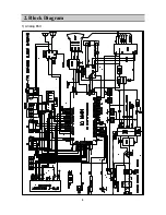
Page 4: ...4 2 Block Diagram 1 Analog Part ...
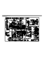
Page 19: ...19 7 Schametic Diagram 1 ALALOG MAIN PART ...
Page 20: ...20 Schametic Diagram 2 POWER PART ...
Page 21: ...21 Schametic Diagram 3 DIGITAL MAIN PART 1 ...
Page 22: ...22 Schametic Diagram 3 DIGITAL MAIN PART 2 ...
Page 23: ...23 Schametic Diagram 3 DIGITAL MAIN PART 3 ...
Page 24: ...24 8 Printed Circuit Board 1 Main PCB ...
Page 25: ...25 Printed Circuit Board 2 Power PCB ...
Page 26: ...26 Printed Circuit Board 3 Digital PCB Top ...
Page 27: ...27 Printed Circuit Board 4 Digital PCB Bottom ...
Page 28: ...28 Printed Circuit Board 5 CRT PCB 6 Union PCB ...
Page 29: ...29 9 Mechanical Exploded Diagram _ p p ª ø L fl T Œx bª Ø L fi Ø p fi Ø 9 p L ...


