17
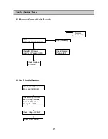
5. Remote Control Unit Trouble
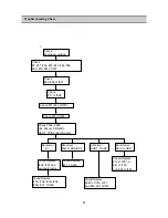
Trouble Shooting Charts
Check
Battery of Remote Control
Check IR of Preamp
And Vcc of Preamp (IC01)
Check/Replace
#37 of I501
Replace Battery
Check/Replace
Preamp(IC01)
Abnormal
Normal
Check connection of
MAIN and DECODER
Check voltage of +1.8V
line. If voltage value is
under +1.56V, check
the regulator I506
Check voltage of CE202.
Check Short RC321
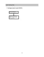
6. No Ci Initialization
Summary of Contents for DUA-3270GB
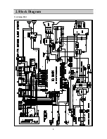
Page 4: ...4 2 Block Diagram 1 Analog Part ...
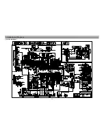
Page 19: ...19 7 Schametic Diagram 1 ALALOG MAIN PART ...
Page 20: ...20 Schametic Diagram 2 POWER PART ...
Page 21: ...21 Schametic Diagram 3 DIGITAL MAIN PART 1 ...
Page 22: ...22 Schametic Diagram 3 DIGITAL MAIN PART 2 ...
Page 23: ...23 Schametic Diagram 3 DIGITAL MAIN PART 3 ...
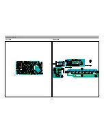
Page 24: ...24 8 Printed Circuit Board 1 Main PCB ...
Page 25: ...25 Printed Circuit Board 2 Power PCB ...
Page 26: ...26 Printed Circuit Board 3 Digital PCB Top ...
Page 27: ...27 Printed Circuit Board 4 Digital PCB Bottom ...
Page 28: ...28 Printed Circuit Board 5 CRT PCB 6 Union PCB ...
Page 29: ...29 9 Mechanical Exploded Diagram _ p p ª ø L fl T Œx bª Ø L fi Ø p fi Ø 9 p L ...


