background image

2

Caution

CAUTION

RISK OF ELECTRIC SHOCK

DO NOT OPEN

CAUTION : TO REDUCE THE RISK OF ELECTRIC SHOCK,

DO NOT REMOVE COVER (OR BACK).

NO USER-SERVICEABLE PARTS INSIDE.

REFER SERVICING TO QUALIFIED SERVICE PERSONNEL.

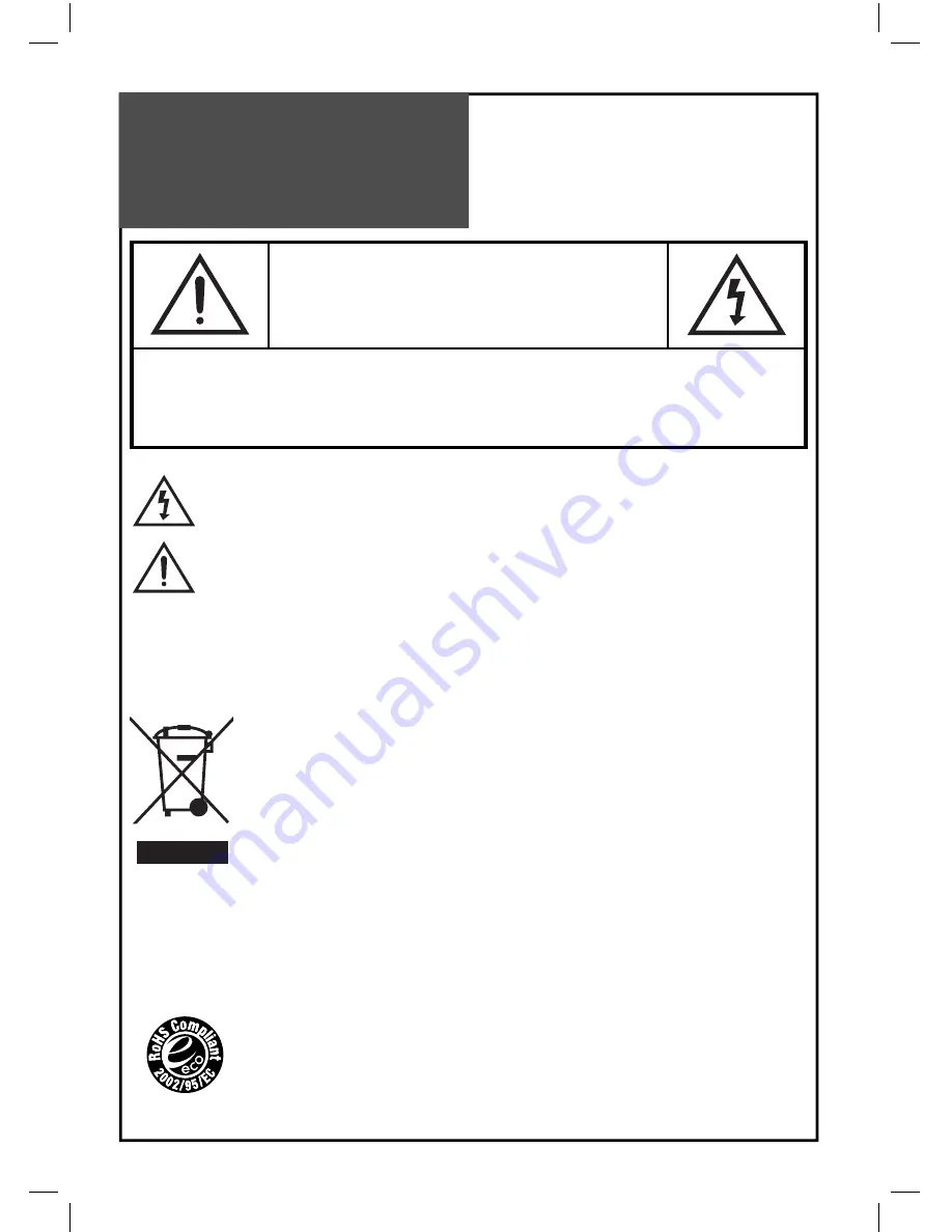
 The lightning flash with arrowhead symbol, within an equilateral triangle, is intended to alert the user 

to the presence of uninsulated “dangerous voltage” within the product’s enclosure that may be of suffi-
cient magnitude to constitute the risk of an electric shock.

 The exclamation point within an equilateral triangle is intended to alert the user to the presence of im-

portant operating and servicing instructions in the literature accompanying the appliance.

WARNING:


TO REDUCE THE RISK OF FIRE OR ELECTRIC SHOCK HAZARD, DO NOT EXPOSE THIS APPLI-
ANCE TO RAIN OR MOISTURE.

CAUTION :


TO PREVENT ELECTRIC SHOCK, MATCH WIDE BLADE OF PLUG TO WIDE SLOT, FULLY IN-
SERT.

DISPOSAL OF USED ELECTRICAL & ELECTRONIC EQUIPMENT
(Europe only)

 The meaning of the symbol on the product, its accessory or packaging indicates that 

this product shall not be treated as household waste. Please dispose of this equipment 
at your applicable collection point for the recycling of electrical & electronic equipments 
waste. In the European Union and Other European countries which there are separate 
collection systems for used electrical and electronic product. By ensuring the correct 
disposal of this product, you will help prevent potentially hazardous waste to the en-
vironment and to human health, products could otherwise be caused by unsuitable 
waste handling of this products. The recycling of materials will help conserve natural 
resources. Please do not therefore dispose of your old electrical and electronic equip-
ment with your household waste. For more detailed information about recycling of 
this product, please contact your local city office, your household waste disposal serv-
ice or the shop where you purchased the product.

RoHS (Directive 2002/95/EC) Compliant

This environment-friendly product does not contain the EU RoHS restricted substanc-
es (Pb, Hg, Cd, Cr6+, PBB, and PBDE).

Summary of Contents for DLP-26C2F Series

Page 1: ...GB LCD TELEVISION INSTRUCTION MANUAL DLP 26C2Fxx DLP 26C3Fxx DLP 32C1Fxx DLP 32C2Fxx DLP 32C3Fxx DLP 32C5Fxx DLP 32C6Fxx DLP 32C7Fxx DLP 37C3Fxx DLP 37C7Fxx...

Page 2: ...The meaning of the symbol on the product its accessory or packaging indicates that this product shall not be treated as household waste Please dispose of this equipment atyourapplicablecollectionpoint...

Page 3: ...from overheating Do not cover the ventilation openings in the cabinet and never place the set in a con ned space such as a built in cabinet unless proper ventilation is provided Leave a minimum 10 cm...

Page 4: ...electrodes and requirements for the grounding electrode 16 Servicing Do not attempt to service thisTV yourself as opening or removing covers may expose you to dangerous voltage or other hazards Refer...

Page 5: ...e product unplug the unitfromtheoutletduringa lightningstorm orwhenitis leftunattendedandunused for a long period of time Donotputonorusetheprod uctnearwaterandmoisture suchasinabathroom wash bowl etc...

Page 6: ...roductisinternal lyoverheated Theproductshouldbesituat edawayfromanyheatsource suchasradiators heatregis ters stoves orotherproducts thatproduceheat Do not put heavy items on thepowerleadsinceitmay re...

Page 7: ...eTV Broadcasting Connection 18 Name of Each Part 19 Basic Guide Parts of the Remote Controller 21 MethodTo Use Basic Menu 23 To WatchTV 24 Setting UpTV Stations 26 Selection of AV and Multimedia Input...

Page 8: ...thodofwirearrangement 1 Assemble the cable holder enclosed on the back ofTV PICTURE1 ASSEMBLY METHOD After you push the peg part of cable holder A in the hole rotate the cable holder clockwise at an a...

Page 9: ...GE IS NOT CLEAR Unclear screen image and bad reception may be a cause of wrong antenna connection Be sure to check its direction and place when installing 2 Connect the combining adapter to the antenn...

Page 10: ...tenna socket and x it rmly by turning it to the right Antenna socket at the left side of the TV set Antenna socket on the wall ANT CABLE When a feeder cable is used Plug the coaxial cable to the anten...

Page 11: ...tdoor Antenna connection such as VHF or and UHF may be necessary for installation at private houses Single Antenna Connection VHF Antenna UHF Antenna Back of the tv set ANT CABLE Separate Antenna Conn...

Page 12: ...me time TheTV set will only detect the S Video mode If your AV device has both Video OUT terminal and S Video OUT terminal the S Video connection is recom mended for better picture quality Connecting...

Page 13: ...shown in the picture below 3 Turn on theTV set and camcorder video game 4 Select AV3 S video mode using the AV button of the Remote controller or button of theTV set Back of the tv set Video game Camc...

Page 14: ...e Back of the tv set DVD Note Whenyouconnectwiththecomponentvideo please check the colour of the cable between the DVD and TV set When connecting with a S Video cable and RCA cable Note If S video and...

Page 15: ...OMPONENT Pr R L Pb Y HDMI INPUT AV1 AV2 PC INPUT PC AUDIO AV3 L AUDIO R COMPONENT Pr R L Pb Y S VIDEO STB SetTop Box Connection When connecting with a HDMI cable Back of the tv set Set Top Box When co...

Page 16: ...andTV set 4 Select PC mode by pressing the MULTIMEDIA button on the remote control or button of theTV set Back of the tv set PC When connecting with a HDMI cable 1 First adjust resolution of the PC Re...

Page 17: ...If these problems hap pen contact the graphic card company for help Multi input resolution available in LCDTV Resolution V freq HDMI PC D Sub Component Standard 640 X 480 60Hz o o x 72Hz o o x 75Hz o...

Page 18: ...andinstalled a cable receiver You may make the connection to either the Component input or SCART input AV1 or AV2 Cable TV Broadcasting Station Input CATV Receiver Antenna Input Connection Watching ca...

Page 19: ...s volume or to move the cursor in the menu PR Buttons Use these buttons to change channels on yourTV or to move the cursor in the menu POWER ON button Use this button to change fromTV STAND by mode t...

Page 20: ...20 HDMI INPUT AV1 AV2 PC INPUT PC AUDIO AV3 L AUDIO R COMPONENT Pr R L Pb Y S VIDEO Name of Each Part Side and Rear Panel Side Panel Rear Panel...

Page 21: ...ectly inTV mode Note When the current state is ST BY you can turn on the TV using a digit key Then a PROGRAMME is selected accord ing to digit number 7 S EFFECT Using this button you can listen to the...

Page 22: ...formation InTV mode the Programme number Sound and Clock 23 DYNAMIC BASS Using this button you can enhance the bass 24 TEXT see page 43 25 MGDI Using this button you can see MGDI DEMO screen Inserting...

Page 23: ...is selected the relevant sub items are displayed upward 1 Press the MENU button The main menu appears if you press the MENU button 2 Press the button You may setup according to the directions on the s...

Page 24: ...numberbuttonforchannelselection For example to watch channel No 9 Press the number button 0 and 9 If pressing only number 9 it takes a longer time to select the chan nel To suddenly turn sound off Pre...

Page 25: ...lat er time by entering the LANGUAGE menu Page 39 1 Turning on theTV Plug AC Cord into a power outlet The Stand By LED lamp turns on in red colour Press button of the main body or POWER but ton on the...

Page 26: ...Setting UpTV Stations AutoTuning All stations that can be received are stored by this method It is recommended that you use Auto tuning during in stallation of this set 1 Press the MENU button to sele...

Page 27: ...lect PR number you want to store with buttons on the remote control A tuning screen will appear and cursor will move from left to right from right to left If you want to stop tun ing press the MENU bu...

Page 28: ...hannels in the Setup menu Pressthe PR buttonstoselectaprogramnumber you want Move to SETUP in the Install menu Select the colour and sound system which you want Search a real channel with buttons 2 En...

Page 29: ...Move to EDIT in the Install menu Movetheselectionbartotheprogramnumbertode lete with the or buttons Press the Delete Yellow button 2 Moving the program positions Move to EDIT in the Install menu Pres...

Page 30: ...AV button on the remote controller The screen changes as follows TV AV1 AV2 AV3 S Video TV Note Cautions in menu setup The menu disappears if you do not operate any button for about 25 seconds from th...

Page 31: ...n put table Multimedia Input Format Resolution V freq HDMI PC D Sub Component Standard 640 X 480 60Hz o o x 72Hz o o x 75Hz o o x VESA Standard 800 X 600 60Hz o o x VESA Standard 72Hz o o x VESA Stand...

Page 32: ...g the NORMAL button The screen changes as follows Normal I Normal II Favourite Normal I The screen adjustment status changes as the following screens are displayed sequentially whenever pressing the N...

Page 33: ...PICTURE menu Whenever pressing the button you can select in order Brightness Contrast Colour Sharpness and ColourTemp The screen appears as on the right if pressing the buttons after selecting items d...

Page 34: ...ding on the signal information of a broadcasting station 16 9 16 9 will display a true 16 9 anamorphic picture with no aspect distortions 14 9 14 9 will display a 14 9 picture at its standard 14 9 siz...

Page 35: ...position of displayed image 2 Adjustment of theV Position Move to V Position in the Screen menu Press the buttons to adjust the vertical position of displayed image 3 Adjustment of the Phase Move to P...

Page 36: ...nd modes 1 Sound mode selects what you want Press the SOUND button then the sound status changes as followed Normal Speach Music Favourite Normal Note Normal normally recommended sound Favourite Allow...

Page 37: ...the Favourite mode Equalizer High quality sound range adjustment method used for audio product 120Hz 500Hz Low sound range 1 5KHz 5KHz Middle sound range 10KHz High sound range 2 Select Balance Mode M...

Page 38: ...you can switch to MONO by pressing the button Then the colour of MONO character will change to Red In Mono reception the depth of sound is improved To switch back to stereo press the button again Note...

Page 39: ...LGARIAN POSITION ACCESS EXIT FUNCTION Selection of Language Selection of Language When you rst turn on theTV set the window of language selection is displayed automatically 1 Press the MENU button and...

Page 40: ...more whenTV is AC off 2 Automatic clock setting and correction Move toTimer in the Function menu Press the button to move to the Auto Clock Select the Auto Clock to Yes Choose the Auto Clock Pr using...

Page 41: ...einthesamewayasabovefortheClock The set will turn off at the selected time Note This function is very convenient since the TV automat ically turns off at the xed time 5 Sleep Mode Bypressingthe SLEEP...

Page 42: ...without the remote control IfTV set is set up Child Lock LED will cycle through red off for the ST BY mode IftheChildLockis On thenthesetcanonlybeswitched back on using the remote control One can mov...

Page 43: ...D symbol appears and the contents of the subpage shown are kept on the screen and no longer updated or switched to other subpages Pressing the HOLD button again the current subpage appears CALLING UP...

Page 44: ...y and if not adjust the an tenna toward the broadcasting station Picture has snow noise Check the antenna or its connection is correct and if not correct the antenna fault or connection cable fault Ch...

Page 45: ...requency on the table not listed then no picture will be displayed NO SIGNAL ap pears on the screen Ensure that the signal cable is rmly connected to PC andTV Image is not clear Adjust the PHASE contr...

Page 46: ...mm 0 600 mm Contrast Ratio 4000 1 5000 1 5000 1 Dimension W x H x D 676 x 530 x 230 mm 806 x 626 5 x 250 mm 940 x 720 x 328 5 mm Power Consumption Remarked in the back of product TV System PAL B G D...

Page 47: ...DMP3994500...

Reviews: