background image

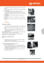
ting and operating the lawnmower;
-If lawnmower starts to vibrate abnormally (check immediately);
20. Stop the engine and disconnect the spark plug wire, make sure that allmoving parts have come 
to a complete stop and, where a key is fitted removethe key:
-Whenever you leave the lawnmower;
-Before refueling;
21. Reduce the throttle setting during engine shut down and, if the engine isprovided with a shut-off 
valve, turn the fuel off at the conclusion of mowing;
22. Go slow when using a trailing seat.

Maintenance and storage

1. Keep all nuts, bolts and screws tight to be sure the equipment is in safeworking condition;
2. Never store the equipment with petrol in the tank inside a building wherefumes can reach an open 
flame or spark;
3. Allow the engine to cool before storing in any enclosure;
4. To reduce the fire hazard, keep the engine, silencer, battery compartment andpetrol storage area 
free of grass, leaves, or excessive grease;
5. Check the grass catcher frequently for wear or deterioration;6.Replace worn or damaged parts 
for safety;
7. If the fuel tank has to be drained, this should be done outdoors.

8. ADJUSTMENT

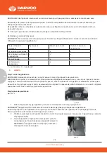
Setting the cutting height As shown in Fig 17

CAUTION! Adjust the cutting height only when the engine is switch off the spark plug Boot has been 
pulled. 

The cutting height is centrally adjusted with Cutting height adjusting handle. Different cutting 
Heights can be selected. 

Pull the adjusting handle out and select the desired cutting height. The handle snaps onto the 
desired position.

From position 1 to position 7. The cutting height range from 25mm to 75 mm.

ting and operating the lawnmower;
-If lawnmower starts to vibrate abnormally (check immediately);
20. Stop the engine and disconnect the spark plug wire, make sure that allmoving parts have come 
to a complete stop and, where a key is fitted removethe key:
-Whenever you leave the lawnmower;
-Before refueling;
21. Reduce the throttle setting during engine shut down and, if the engine isprovided with a shut-off 
valve, turn the fuel off at the conclusion of mowing;
22. Go slow when using a trailing seat.

Maintenance and storage

1. Keep all nuts, bolts and screws tight to be sure the equipment is in safeworking condition;
2. Never store the equipment with petrol in the tank inside a building wherefumes can reach an open 
flame or spark;
3. Allow the engine to cool before storing in any enclosure;
4. To reduce the fire hazard, keep the engine, silencer, battery compartment andpetrol storage area 
free of grass, leaves, or excessive grease;
5. Check the grass catcher frequently for wear or deterioration;6.Replace worn or damaged parts 
for safety;
7. If the fuel tank has to be drained, this should be done outdoors.

8. ADJUSTMENT

Setting the cutting height As shown in Fig 17

CAUTION! Adjust the cutting height only when the engine is switch off the spark plug Boot has been 
pulled. 

The cutting height is centrally adjusted with Cutting height adjusting handle. Different cutting 
Heights can be selected. 

Pull the adjusting handle out and select the desired cutting height. The handle snaps onto the 
desired position.

www.daewoopower.bg

25

BG

изпаренията


могат


да


бъдат


в


достъп


с


открити


пламъци


или


искри

.

3)  Позволете


на


двигателя


да


се


охлади


преди


да


го


приберете


за


съхранение

.

4)  За


да


редуцирате


риска


от


пожар,


пазете


двигателя,


заглушителя,


отделението


за


акумулатора


и


зоната,


в


която


съхранявате


бензина


свободни


от


трева,


листа,


или


прекалено


омазняване

.

5)  Проверявайте


често


колектора


за


трева


за


износване


или


влошаване

6)  Подменяйте


износените


или


повредени


части


за


безопасна


работа

.

7)  Ако


трябва


да


подсушите


резервоара,


това


трябва


да


се


прави


навън

.

7. 

СГЛОБЯВАНЕ

Сглобяване на дръжката

1. 

Затегнете


долната


дръжка


към


рамката


като


използвате


двата


болта


и


малките


гайки


на


всяка


страна,


както


е


показано


на


фиг

. 2

2. 

Разгънете


горната


дръжка


и


я


фиксирайте


към


долната


използвайки


големите


болтове


за


всяка


страна,


както


е


показано


на


фиг

. 3

ЗАБЕЛЕЖКА

уверете


се,


че


водачът


на


стартерното


въже


е


от


дясната


страна


на


дръжката,


когато


стоите


зад


косачката

.

Прикрепете


жилата


към


долната


дръжка


с


клипс


/доставя


се


с


комплекта/

както


е


показано


на


фиг

. 4.

Сглобяване на колектора за трева

Фиг

. 5

1. 

Повдигнете


капака


на


задния


борд


за


изхвърляне


с


едната


ръка


и


закачете


колектора


за


трева

2. 

Затворете


капака,


за


да


стабилизирате


колектора


на


място

.

Сглобяване


на


приставката


за


мулчиране


Фиг

. 6

1. 

Махнете


колектора


за


трева

2. 

Плъзнете


пластмасовата


приставка


за


мулчиране


(фиг

6)


в


улея


за


изхвърляне


(фиг

7),


докато


се


заключи


на


мястото


си

Внимавайте,


когато


асемблирате,


уверете


се,


че


приставката


е


наистина


застопорена


на


място

.

3. 

Освободете


щифта


(фиг

8),


той


ще


се


затвори


и


ще


покрие


мулчиращата


приставка

.

24

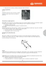
7. ASSEMBLY

Assembling the handle
1. Fasten the lower handle toThe device by using 
two bolts andtwo small knobs on each side as 
shown in Fig 2.
46cm cutting witch has one knob on each side)

2.Unfold the upper handle and fix it to lower 
handleby using the big knobs and the 
blots on each sideas shown in Fig3

NOTE: Make sure the rope guide is on the right 
handle, when you stand behind the mower.

Fasten the connection cord with clip 
As shown in Fig 4Fix the connection cord 
to the lower handle With the cord clip .(supplied)

Assembling the grass bag onto the mower 
As shown in Fig 6

1.Lift the rear discharge cover with one hand 
andhook in the grass bag.2.Release the rear 
discharge cover to secure thegrass bag in position.

Assembling the mulching plug (Fig 8)

1. Remove the grass bag
2. Push the plastic mulchingplug
(Fig 8) into the dischargechute (Fig 9) until it is locked inplace. 
(Please pay attention to thelock when assembling.
3. Then release the flap(Fig 10), 
it will close Back to cover themulching plug.

Assembling the side discharge chute As shown in Fig 11

Fig 2 

Fig 3 

Fig 4

Fig 6

Fig 8

Fig 9

Fig 10

фиг

.2

фиг

.3

фиг

.4

фиг

.5

фиг

.6

фиг

.7

фиг

.8

7. ASSEMBLY

Assembling the handle
1. Fasten the lower handle toThe device by using 
two bolts andtwo small knobs on each side as 
shown in Fig 2.
46cm cutting witch has one knob on each side)

2.Unfold the upper handle and fix it to lower 
handleby using the big knobs and the 
blots on each sideas shown in Fig3

NOTE: Make sure the rope guide is on the right 
handle, when you stand behind the mower.

Fasten the connection cord with clip 
As shown in Fig 4Fix the connection cord 
to the lower handle With the cord clip .(supplied)

Assembling the grass bag onto the mower 
As shown in Fig 6

1.Lift the rear discharge cover with one hand 
andhook in the grass bag.2.Release the rear 
discharge cover to secure thegrass bag in position.

Assembling the mulching plug (Fig 8)

1. Remove the grass bag
2. Push the plastic mulchingplug
(Fig 8) into the dischargechute (Fig 9) until it is locked inplace. 
(Please pay attention to thelock when assembling.
3. Then release the flap(Fig 10), 
it will close Back to cover themulching plug.

Assembling the side discharge chute As shown in Fig 11

9. OPERATION

Start and stop the engine

WARNING: the blade begins to rotate as soon as the engine is started.

  Never refuel while the engine is running.

  Risk of injury . do not open or remove safety shields while engine is running.

  Wearing ear protection , eye protection when operating.

  Hot surfaces will burn finger or palms.

NOTE: When use side discharge function. First need remove the grass
Bag and plug the mulching plug.
1. Lift the side discharge cover with
One hand and hook in the side dischargeDuct with the other hand.
2. Release the side discharge cover tosecure the duct in position.

Assembling the cup holder (optional)
As shown in Fig 13
1. Take out the plastic panel (1) from the box.
2. Align the mounting holes on the plastic panel
with the mounting holes on the upper-handle (2).
3. Fix the plastic panel with the bolts
and nuts (3) and (4) provided.

Checking the engine oil level And filling with engine 
oil As shown in Fig 15-16

Summary of Contents for DLM4600SPL

Page 1: ...nes take care as rotating one blade can cause otherblades to rotate Operation 1 Do not operate the engine in a confined space where dangerous carbonmonoxide fumes can collect 2 Mow only in daylight or...

Page 2: ...the spark plug wire make sure that all moving parts have come to a complete stop and where a key is fitted removethe key Before clearing blockages or unclogging chute Before checking cleaning or worki...

Page 3: ...ver to secure thegrass bag in position Assembling the mulching plug Fig 8 1 Remove the grass bag 2 Push the plastic mulchingplug Fig 8 into the dischargechute Fig 9 until it is locked inplace Please p...

Page 4: ...ling fuel There should be no fuel in thefiller neck 4 Clean up any overflow or splashes of petrolbefore starting the engine 5 Tighten the filler cap after filling fingertight on If petrol is spilled d...

Page 5: ...lace worn or damaged parts safety the fuel tank has to be drained this should be done outdoors DJUSTMENT ing the cutting height As shown in Fig 17 UTION Adjust the cutting height only when the engine...

Page 6: ...is purpose Refuel outdoors only and do not smoke while refueling Add fuel before starting the engine Never remove the cap of the fuel tank oradd petrol while the engine is running or when the engine i...

Page 7: ...ve grease Check the grass catcher frequently for wear or deterioration 6 Replace worn or damaged parts safety the fuel tank has to be drained this should be done outdoors 6 For wheeled rotary machines...

Page 8: ...using two bolts andtwo small knobs on each side as shown in Fig 2 46cm cutting witch has one knob on each side 2 Unfold the upper handle and fix it to lower handleby using the big knobs and the blots...

Page 9: ...be filled with the correct grade of oil and petrol before tarting the engine NOTE Running the engine with a low oil level will cause engine damage It is recommend that high etergent premium quality 4...

Page 10: ...verflow or splashes of petrolbefore starting the engine 5 Tighten the filler cap after filling fingertight on 26 Wipe away any spilt oil 4 Align the ribs of the cap with the groove of the filler neck...

Page 11: ...STMENT Setting the cutting height As shown in Fig 17 CAUTION Adjust the cutting height only when the engine is switch off the spark plug Boot has bee pulled The cutting height is centrally adjusted wi...

Page 12: ...e As shown in Fig 20 Release the engine start stop lever it will return to its Initial position the engine will automatically switch off 9 OPERATION Start and stop the engine WARNING the blade begins...

Page 13: ...e scatteredefficiently do not cut high or wet grass When you have been cutting forseveral minutes please stop the mower and Fig21 To clean a flooded engine NOTE if the engine won t start after you hav...

Page 14: ...ntains a lot of dust the air filter should be checked more frequently www daewoopower bg 14 EN www daewoopower bg 14 EN 30 clean the blade and the deck 9 Do not remove grass debris in the mower casing...

Page 15: ...e oil Start the engine and allow it to run riefly top the engine wait one minute and check the oil level Top up if necessary Note see more in ngine manual Replacing the blade or safety reasons you sho...

Page 16: ...p turn of the blade must project into the motor compartment Storing the Lawnmower for Short Periods The lawnmower can be stored for short periods of time less than 15 days without performing any stora...

Page 17: ...ait until the blade has come to a stop Caution Improper repairs can result in the product functioning unsafely This endangers yourself and your environment Faults which cannot be rectified with the ai...

Page 18: ...e may be flooded y r d d n a g u l p e v o m e R Engine runs unsteadily Air filter is soiled Clean the air filter Spark plug is soiled g u l p k r a p s e h t n a e l C Uneven mowing results Blade is...

Page 19: ...www daewoopower bg 19 BG 1 20 2 21 3 22 4 22 5 22 6 23 7 25 8 27 9 28 10 30 11 33 12 34 13 41...

Page 20: ...lever 5 Fixing knob w ith square neck blot 6 Lower handle 7 Grass box 8 Fuel tank cap 9 Primer 10 Front decorative cover 11 Height adjusting handle 12 Rear wheel 13 Engine oil cap 14 Side discharge c...

Page 21: ...e any other use is Deemed to be a case of misuse The user operator and not the Manufacturer will be liable for any damage or injuries of any kind caused as a result of this Please note that our equipm...

Page 22: ...ing Wearing ear protection eye protection when operating Hot surfaces will burn finger or palms 5 WARNING SYMBOLS ON THE MACHINE WARING To reduce the risk of injury user must read instruction manual T...

Page 23: ...r exhaust gas contains toxic substances Do not start or run engine indoors or in an enclosed area even if windows and doors are open Conforms to relevant safety standards Waste electrical products sho...

Page 24: ...lace all fuel tank and container caps securely 4 Replace faulty silencers 5 Before using always visually inspect to see that the blades blade bolts andcutter assembly are not worn or damaged Replace w...

Page 25: ...bling the grass bag onto the mower As shown in Fig 6 1 Lift the rear discharge cover with one hand andhook in the grass bag 2 Release the rear discharge cover to secure thegrass bag in position Assemb...

Page 26: ...2 3 Fix the plastic panel with the bolts and nuts 3 and 4 provided Checking the engine oil level And filling with engine oil As shown in Fig 15 16 CAUTION The following procedures and adjustments must...

Page 27: ...e of oil and petrol before starting the engine WARNING Refuel in a well ventilated area with the engine stopped Do not smoke or allow flame or sparks in the area where the engine is refueled or where...

Page 28: ...the cutting height As shown in Fig 17 CAUTION Adjust the cutting height only when the engine is switch off the spark plug Boot has been pulled The cutting height is centrally adjusted with Cutting hei...

Page 29: ...plug carefully by hand to avoid cross threading After the plug is seated tighten 1 8 to 1 4 turn with socket spanner of sparkplug to compress the washer 1 Pull the engine start stop lever toward uppe...

Page 30: ...TE Before placing the lawn mower on its side fully drain the fuel tank using a petrol extraction pump Do not tilt the lawn mower by more than 90 degrees Maintenance of the spark plug As shown in Fig 2...

Page 31: ...afety reasons you should only ever have your blade sharpened balanced and mounted by an authorised service workshop For optimum results it is recommended that the blade should be inspected once a year...

Page 32: ...Align the ribs of the cap with the groove of the filler neck then rotate 1 4 turn to secure it Filling with engine fuel As shown in Fig 15 CAUTION Always use clean fresh unleaded petrol Purchase fuel...

Page 33: ...ed ll the adjusting handle out and select the desired cutting height The handle snaps onto the sired position om position 1 to position 7 The cutting height range from 25mm to 75 mm tting required fun...

Page 34: ...g put the starter ropeInto the rope guide To stop the engine As shown in Fig 20 Release the engine start stop lever it will return to its Initial position the engine will automatically switch off ATIO...

Page 35: ...Install the spark plug carefully by hand to avoid cross threading After the plug is seated ten 1 8 to 1 4 turn with socket spanner of sparkplug to compress the washer ull the engine start stop lever...

Page 36: ...er it is time to empty the grass bag NOTE Before taking off the grass bag switch off the engine and wait untilthe blade has come to a stop 1 To take off the grass bag use one hand to lift up ejector f...

Page 37: ...e without the air filter element installed 1 Remove the air cleaner outside cover A Be carefulto prevent dirt and debris from falling into the aircleaner assembly 2 Separate the Air Filter A from the...

Page 38: ...at the end of every season To do so remove the used engine WARNING If the blade is cracked or damaged replace it with a new one WARNING Don t hold the blade by hand directly NOTE Maintain the sharpnes...

Page 39: ...arranty you can also endanger yourself and your environment oil from a warm engine and refill with fresh oil4 Clean the cooling fins of the cylinder and the housing 5 Be sure to clean the entire machi...

Page 40: ...www daewoopower bg 40 BG 10 6 M5x30 10 6 M5x30...

Page 41: ...following standards and The under signed is responsible for the of technical BG 150 2 6 kW 460 mm DLM4600SPL DM46S D150 GBR address 15 F 100 Queen s Road Central Central Hong Kong Harmonized standard...

Page 42: ...www daewoopower bg 42 BG WARRANTY 361 0893 383 798 1 3 052 575400 248 032 946065 42 082 870104 37 042 600699 5000 062 690003 90 064 600082...

Page 43: ...www daewoopower bg 43 BG 24 6 6 12 6...

Page 44: ...www daewoopower bg 44 BG 1 1 2022 6 6...

Page 45: ...www daewoopower bg 45 BG...

Page 46: ...www daewoopower bg 1784 1 51 359 2 81 77 600 359 2 81 77 601...

Reviews: