8
TROUBLE SHOOTING GUIDE
1. TROUBLE SHOOTING FLOW CHART
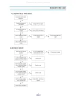
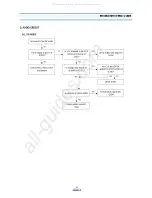
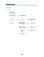
A. POWER CIRCUIT
When changing the parts which are out of order, first, remove the power plug from the socket and then discharge the
voltage across between both terminals of C803. (Use an external approximately 20 resistance)
When check the primary circuit by using the oscilloscopes insulate the oscilloscope properly (Use the insulating trans-
former)and GND must be connected GND into the primary GND (But there is no connection when checking the seca-
ondary circuit.
When changing M801, check FUSE and ceramic resistor properly.
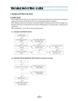
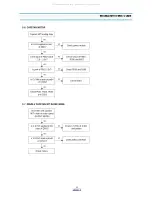
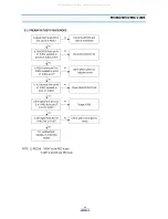
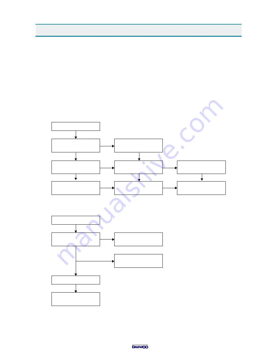
A-1. CHECKING THE PRIMARY CIRCUIT.
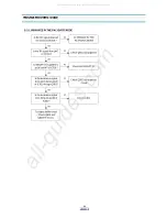
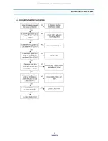
A-2. CHECKING THE SECONDARDARY CIRCUIT.(Before secondary circuit open).
No output voltage
YES
Is the voltage applied to
CN11?
NO
Check F801, L801, L802
C803, D801, R801
YES
YES
Is the v15V at pin3
of IC11?
NO
Is the voltage above 10V
at pin3 of IC11?
NO
Is the voltage 0V at pin3
of IC11?
YES
YES
YES
Check the secaondary
circuit
NO
( A )
NO
Check R14, R15, T11
R13, D11, L12
(A)
YES
Check each output voltage
NO
Check transformer of no
output stages
YES
NO
Check the diode of no
output stages
YES
Check the CN11
YES
Check the coil, condensor
of no output stages
All manuals and user guides at all-guides.com
Summary of Contents for DV-S123W Series
Page 33: ...32 PRINTED CIRCUIT BOARD 1 PCB MAIN All manuals and user guides at all guides com...
Page 34: ...33 PRINTED CIRCUIT BOARD 2 PCB POWER SMPS All manuals and user guides at all guides com...
Page 40: ...39 EXPLODING VIEWS PARTS LIST 1 PACKING AS All manuals and user guides at all guides com...


