6
GENERAL ADJUSTMENT
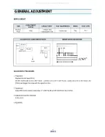
SERVO CIRCUIT
ADJUSTMENT PROCEDURE
1. Preparation
Playback the test tape (DP-2).
Set the oscilloscope to the CHOP mode. Connect CH1 to the V.SW PULSE (TJ591) and CH2 to the VIDEO OUT
(TJ391) and trigger the scope with the signal from CH1.
2. Adjustment
Adjust R591 to the positive rising edge of V.SW PULSE at 6.5H ±0.5H from the V-SYNC.
3. Adjustment Inspection Standard
6.5H ± 0.5H
4. REMARKS
ITEM
ADJUSTMENT
PARTS
CHECK POINT
TEST EQUIPMENTS
MODE
TEST TAPE
Playback
Phase
R591
TJ591(V.SW)
TJ391(VIDEO OUT)
Oscilloscope
Play
DP-2
LOCATION OF ADJUSTMENT PARTS
OBSERVATION WAVEFORM
MOD
A/V JACK
TJ391
(VIDEO OUT)
PRE-AMP
SMPS
TJ591
(V. SW)
R591
FRONT
All manuals and user guides at all-guides.com
Summary of Contents for DV-S123W Series
Page 33: ...32 PRINTED CIRCUIT BOARD 1 PCB MAIN All manuals and user guides at all guides com...
Page 34: ...33 PRINTED CIRCUIT BOARD 2 PCB POWER SMPS All manuals and user guides at all guides com...
Page 40: ...39 EXPLODING VIEWS PARTS LIST 1 PACKING AS All manuals and user guides at all guides com...


