18
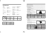
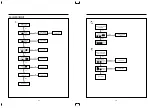
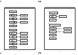
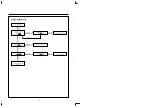
Check each voltage on
M801(SMPS Modute)
Check voltage
C851, C856,
C853, C855
Change of the M801
NO
Check D851, D854, Q851, Q852
NO
Check the main
PCB circuit (+6V) &
Logic PCB circuit (-24V)
YES
YES
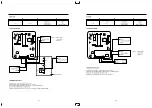
B. CHECKING THE SECONDARY CIRCUIT. (Before secondary circuit open).
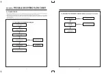
SECTION 3.
TROUBLE SHOOTING FLOW CHART
3-1. POWER CIRCUIT
• When changing the parts which are out of order, first, remove the power plug from the socket and then discharge the
voltage across between both terminals of C807. (Use an external approximately 20K
Ω
resistance)
• When check the primary circuit by using the oscilloscopes insulate the oscilloscope properly (Use the isulating
transformer) and GND must be connected GND into the primary GND (But there is no connection when checking the
secondary circuit).
• When changing M801, check FUSE and Cement resistance properly.
17
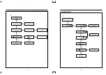
Prepare the instrument
connecting the insulating trans.
Check F801 FUSE.
Is voltage applied to D801?
Is voltage applied to the
both terminals of C807?
Check D801, L801 & L802.
Check R802 &
M801(SMPS Module)
Check the Secondary circuit.
NO
NO
YES
YES
YES
YES
YES
NO output Voltage.
A. CHECKING THE PRIMARY CIRCUIT.
Summary of Contents for DV-F562 Series
Page 19: ......
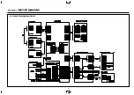
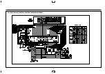
Page 20: ...SECTION 5 CIRCUIT DIAGRAM 5 1 CONNECTION DIAGRAM CIRCUIT 33...
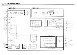
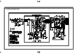
Page 21: ...5 2 POWER CIRCUIT 230V ONLY 34...
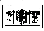
Page 22: ...5 3 POWER CIRCUIT WIDE RANGE 35 M M M M...
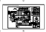
Page 24: ...5 4 SERVO LOGIC CIRCUIT 37 M M...
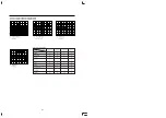
Page 25: ...5 5 LOGIC CIRCUIT WITH SHUTTLE STATION F542 F342 SERIES 38 1 3 2 1 2 3...
Page 26: ...5 6 LOGIC CIRCUIT F442 F242 F462 F262 F402 1 F202 1 SERIES 39 1 2 3 3 2 1...
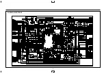
Page 27: ...5 7 LOGIC CIRCUIT F562 F362 SERIES 40...
Page 28: ...5 8 LOGIC CIRCUIT F402 2 F202 2 SERIES 41 1 2 3 3 2 1...
Page 29: ......
Page 30: ......
Page 31: ...5 11 PIF CIRCUIT 44 M M M...
Page 32: ......
Page 34: ...5 13 VIDEO CIRCUIT 47...
Page 35: ......
Page 36: ...5 14 OSP CIRCUIT 48 5 15 COLOR CONVERTER 49...
Page 37: ...5 17 IF MODULE CIRCUIT 51 5 16 LINEAR AUDIO CIRCUIT 50 M M M M M M M...
Page 38: ......
Page 39: ...5 19 VPS PDC CIRCUIT AUTO SET 53 5 18 VPS CIRCUIT 52...
Page 40: ...5 21 REMOCON CIRCUIT VR F2BC 55 5 20 REMOCON CIRCUIT VR F3BC 54...
Page 41: ...5 22 REMOCON CIRCUIT VR F2BT 56...
Page 50: ......
Page 51: ......
Page 52: ......


