30
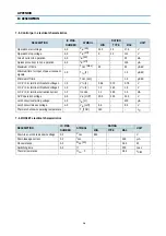
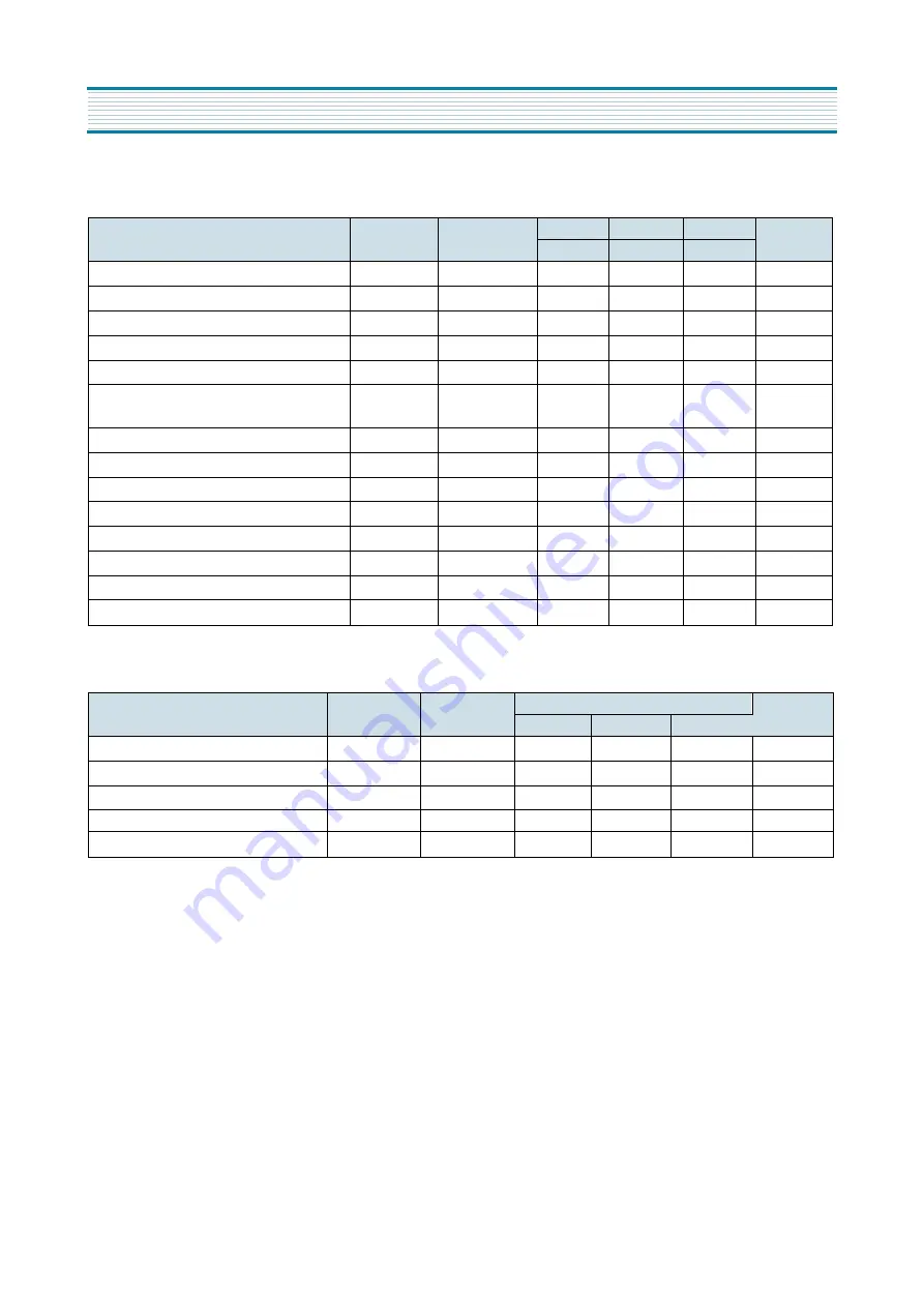
7-5. Control part - electrical characteristics
7-6. MOSFET electrical characteristics
DESCRIPTION
IC PINS
SYMBOL
RATING
UNIT
NUMBER
MIN.
TYPE
MAX
Operation start voltage
4-5
V
IN
(on)
14.4
16
17.6
V
Operation stop voltage
4-5
V
IN
(off)
9
10
111
V
Circuit current in operation
4-5
I
IN
(on)
-
-
30
mA
Quiescent current in non-operation
4-5
I
IN
(off)
-
-
100
µ
A
Maximum off time
-
T
OFF
(max)
45
-
55
µ
SEC
Minimum time for input of quasi resonant
signals
1-5
T
TH
(2)
-
-
1.0
µ
SEC
Minimum off time
-
T
OFF
(min)
-
-
1.5
µ
SEC
O.C.P./F.B. terminal threshold voltage 1
1-5
V
TH
(1)
0.68
0.73
0.78
V
O.C.P./F.B. terminal threshold voltage 2
1-5
V
TH
(2)
1.3
1.45
1.6
V
O.C.P./F.B. terminal extraction current
1-2
I
OCP/FB
1.2
1.35
1.5
mA
OVP operation voltage
4-5
V
IN
(OVP)
20.5
22.5
24.5
V
Latch circuit sustaining voltage
4-5
I
IN
(H)
-
-
400
µ
A
Latch circuit release voltage
4-5
V
IN
(Loff)
6.6
-
8.4
V
Thermal shutdown operating temperature -
T
j
(TSD)
140
-
-
0
C
DESCRIPTION
IC PINS
SYMBOL
RATING
UNIT
NUMBER
MIN.
TYPE
MAX
Drain-to-source break down voltage
3-2
V
DSS
650
-
-
V
Drain leakage current
3-2
I
DSS
-
-
300
µ
A
On-resistance
3-2
R
DS
(on)
-
-
1.95
W
Switching time
3-2
tf
-
-
250
noec
Thermal resistance
-
O
CH
- F
-
-
0.95
0
C/W
APPENDIX
IC DESCRIPTION
Summary of Contents for DTA-14V1
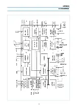
Page 26: ...6 CIRCUIT BLOCK DIAGRAM...
Page 29: ......
Page 30: ...10 EXPLODED VIEW 1 14V3...
Page 31: ...11 EXPLODED VIEW 2 20V3...
Page 32: ...12 EXPLODED VIEW 3 21V3...
Page 33: ...13 PRINTED CIRCUIT BOARD CIRCUIT DIAGRAM 6 SERVO SYSCON CEC CIRCUIT DIAGRAM T DECK...
Page 59: ...19 IC DESCRIPTION APPENDIX...
Page 62: ...22 APPENDIX IC DESCRIPTION...

