


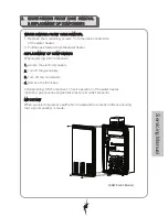


13. LATENT
HEAT EXCHANGER
1. Refer to Frame 2-3.
2.
5.
6.
7.
8.
Reassemble in reverse order.
Check the operation of the water heater.
Refer to Frame 2-3.
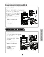
Remove the combustion chamber.
Refer to Frame 13 (1~5)
REPLACEMENT
14. SENSIBLE HEAT EXCHANGER REPLACEMENT
1. Refer to Frame 2-3.
3.
4.
6.
x 7
x 14
Remove the 6 screws to separate
the duct assembly form the sensible
heat exchanger.
Remove the 6 screws to separate the
sensible heat exchanger from
combustion chamber surround.
7.
8.
Fit the new sensible heat exchanger.
Reassemble in reverse order.
Check the operation of the water heater.
Refer to Frame 2-3.
Separate the duct assembly
and latent heat exchanger.
Turn the nut of latent heat exchanger
counter clockwise and then remove
from the duct assembly.
the 7 screws
Fit the new latent heat exchanger.
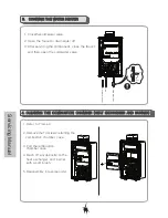
5.
Remove the 14 screws retaining the
combustion chamber case.
2.
3.
4.
Remove the
2 screws to separate the fan from
the combustion chamber.
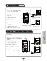
Turn the 2 nuts of cold water inlet pipe &
outlet pipe counterclockwise and then
remove the 5 screws on the gas valve
to separate the combustion chamber.
Remove the 3 screws on the chassis
to separate the combustion chamber.
Separate the combustion chamber.
Latent heat
exchanger
Latent heat
exchanger
Duct assembly
Sensible heat
exchanger
Servicing Manual
Summary of Contents for SHW-13
Page 3: ......
Page 4: ...Supplier outdoor...
Page 5: ...30cm 5cm 5cm 60cm 30cm Ground...
Page 6: ......
Page 7: ...1km Supplier 13 35 13...
Page 8: ...External Main Unit SHW 13 33 Outdoor 57 58 Air Intake SHW 13 26 Model SHW 30 33 Model...
Page 9: ...Indoor 59 60 SHW 30 33 Model SHW 13 26 Model Internal Main Unit SHW 13 33...
Page 13: ...external pipes from freezing Electrical heating elements are used for freeze protection 11...
Page 14: ...External Model Internal Model...
Page 16: ...2 5LPM 2 5lpm 240V 50Hz 15 15 12...
Page 17: ...2 5 LPM 15 15 12...
Page 18: ...1000kPa...
Page 19: ......
Page 20: ......
Page 22: ...101 SHW 30 33 External Model 104 109 111 112 113 114 116 103 102 105 106 107 108 110 115...
Page 23: ...115 116 SHW 30 33 Internal Model...
Page 24: ...214 215 Burner Assembly SHW 30 33 Internal External...
Page 25: ...326 325 327 328 329 Water Line Assembly SHW 30 33 Internal External...
Page 27: ......
Page 32: ......
Page 33: ......
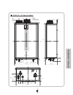
Page 35: ...25mm in 250mm 50cm 50cm 50cm Vent Terminal Internal Model...
Page 37: ...Vent Size 75 100 vent size 45 45cm Min 500mm Exhaust and Air intake terminals...
Page 44: ...200kPa 96 to 482kPa 200kPa 49...
Page 45: ...50...
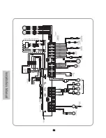
Page 47: ...SHW 30 33 Model 240VAC 5A AC 240V 52...
Page 48: ...SHW 53...
Page 50: ...55...


