background image

6

MMD24S
MMD24B

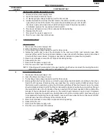
2.  Open the drawer and keep it open.
3.  To discharge high voltage capacitor, wait for 60 seconds.
4.  To test for an open filament, isolate the magnetron from the high voltage circuit. A continuity check across 

the magnetron filament leads should indicate less than  ohm.

5.  To test for a shorted magnetron, connect the ohmmeter leads between the magnetron filament leads 

and chassis ground. This test should indicate an infinite resistance. If there is little or no resistance the 
magnetron is grounded and must be replaced.

6.  Reconnect all leads removed from components during testing.
7.  Reassemble the unit.
8.  Reconnect the power supply cord.
9.  Run the oven and check all functions.

MICROWAVE OUTPUT POWER
The following test procedure should be carried out with the microwave oven in a fully assembled condition.

HIGH VOLTAGES ARE PRESENT DURING THE COOK CYCLE, SO EXTREME CAUTION SHOULD BE 
OBSERVED.

Power  output  of  the  magnetron  can  be  measured  by  performing  a  water  temperature  rise  test. This  test 
should only be used if above tests do not indicate a faulty magnetron and there is no defect in the following 
components or wiring: This test will require a 6 ounce (453cc) measuring cup and an accurate mercury 
thermometer or thermocouple type temperature tester. For accurate results, the following procedure must 
be followed carefully:

.  Fill the measuring cup with 6 oz. (453cc) of tap water and measure the temperature of the water with 

a thermometer or thermocouple temperature tester. Stir the thermometer or thermocouple through the 
water until the temperature stabilizes. Record the temperature of the water.

2.  Place the cup of water in the oven. Operate oven at POWER 0(HIGH) selecting more than 60 seconds 

cook time. Allow the water to heat for 60 seconds, measuring with a stop watch, second hand of a watch 
or the digital read-out countdown.

3.  Remove the cup from the oven and again measure the temperature, making sure to stir the thermometer 

or thermocouple through the water until the maximum temperature is recorded.

4.  Subtract the cold water temperature from the hot water temperature. The normal result should be 28

ο

 to 

54

ο

F (6

ο

 to 30

ο

C) rise in temperature. If the water temperatures are accurately measured and tested 

for the required time period the test results will indicate if the magnetron tube has low power output (low 
rise  in  water  temperature)  which  would  extend  cooking  time  or  high  power  output  (high  rise  in  water 
temperature) which would reduce cooking time. Because cooking time can be adjusted to compensate 
for power output, the magnetron tube assembly should be replaced only if the water temperature rise 
test indicates a power output well beyond the normal limits. The test is only accurate if the power supply 
line voltage is 20 volts and the oven cavity is clean.


MAGNETRON ASSEMBLY TEST

                                . 

Disconnect the power supply cord.

2. 

Open the drawer and keep it open.

3.  To discharge high voltage capacitor, wait for 60 seconds.
4.  A continuity check across the thermal cut-out terminals should indicate a closed circuit unless the 

temperature of the thermal cut-out reaches approximately 293

ο

F(45

ο

C). 


An open thermal cut-out indicates overheating of the oven, exchange the oven thermal cut-out and 
check inside of oven cavity and for improper setting of cooking time or operation of control unit. 
Check for restricted air flow through the vent holes of the oven cavity, especially the cooling fan and 
air guide.

5.  Reconnect all leads removed from components during testing.
6. 

Reassemble the unit.

7.  Reconnect the power supply cord.
8.  Run the unit and check all functions.

CAUTION:  IF THE THERMAL CUT-OUT INDICATES AN OPEN CIRCUIT AT ROOM TEMPERATURE, 

REPLACE THERMAL CUT-OUT.


THERMAL CUT-OUT TEST

                              . 

Disconnect the power supply cord.

Refer to  the disassembly instructions found on Page 27.

TEST PROCEDURES


PROCEDURE 


LETTER 

COMPONENT TEST


Summary of Contents for MMD24B

Page 1: ...y high voltage and current Contact with the following parts may result in a severe possibly fatal electrical shock High Voltage Capacitor High Voltage Power Transformer High Voltage Rectifier and Heat...

Page 2: ...r seal and microwave generation and transmission systems shall be repaired replaced or adjusted by procedures described in this manual before the oven is released to the owner e A microwave leakage ch...

Page 3: ...neccessary covers 2 Open the drawer and keep it open 3 Discharge high voltage capacitor 4 Disconnect the leads to the primary of the power transformer 5 Ensure that the leads remain isolated from othe...

Page 4: ...275 15 ml 9 8 oz of tap water initially at 20 5O C 68O F in the center of the oven cavity The water container shall be a low form of 600 ml 20 oz beaker with an inside diameter of approx 8 5 cm 3 1 2...

Page 5: ...he door brackets and hinges are not defective C The door packing is not damaged D The door is not deformed or warped E There is no other visible damage with the oven Servicing and repair work must be...

Page 6: ...ull power throughout the cooking time P 90 approx 90 of Full Power P 80 approx 80 of Full Power P 70 approx 70 of Full Power P 60 approx 60 of Full Power P 50 approx 50 of Full Power P 40 approx 40 of...

Page 7: ...vided When installing this appliance observe all applicable codes and ordinances Where a two pronged wall receptacle is encountered it is the personal responsibility and obligation of the customer to...

Page 8: ...to the stir fan motor the cooling fan motor and the high voltage componentsarede energized theovenlampremainson and the digital read out displays the time still remaining in the cook cycle when the d...

Page 9: ...ooking Sequence 1 Touch one of the SENSOR pads NOTE The oven should not be operated on sensor immediately after plugging in the unit Wait two minutes before cooking on SENSOR 2 The coil of shut off re...

Page 10: ...TO SOURCE TO LOAD TO LOAD TO SOURCE SWITCHING SWITCH DOOR SENSING SENSOR FAN MOTOR HUMDITY F3 F2 F1 SM FM OL A3 COM N O STIRRER MOTOR OVEN LAMP SECONDARY INTERLOCK SWITCH RY3 RY1 RY2 CAPACITOR xxx F A...

Page 11: ...covers 2 Open the drawer and block it open 3 Discharge high voltage capacitor 4 Replace the Keyboard unit 5 Reconnect all leads removed from components during testing 6 Re install the covers 7 Reconn...

Page 12: ...regurator for drawer motor 8 Disconnect the power supply cord and then remove outer case 9 Open the door and block it open 10 Discharge high voltage capacitor 2 Open the drawer and block it open 3 Dis...

Page 13: ...tor has been burned replace the power unit 7 Examine the touch control transformer with a tester for the presence of layer short circuit check the primary coil resistance which is approximately 151 6...

Page 14: ...n cavity 3 Close the drawer 4 Touch the TIMER CLOCK pad once the POWER LEVEL pad twice and the START pad once And touch the number pads 1 once and the number pad 4 once Now the oven is in the sensor c...

Page 15: ...supply cord 9 Check the sensor cook operation proceed as follows 9 1 Close the door Touch the TIMER CLOCK pad once the POWER LEVEL pad twice and the START pad once And touch the number pads 1 once an...

Page 16: ...igital read out countdown 3 Remove the cup from the oven and again measure the temperature making sure to stir the thermometer or thermocouple through the water until the maximum temperature is record...

Page 17: ...meter should indicate a closed circuit When the monitor switch actuator is pushed by a screw driver through the lower latch hole on the front plate of the oven cavity with the drawer opened in this co...

Page 18: ...E FILAMENT AND HIGH VOLTAGE 2 Open the drawer and block it open 3 To discharge high voltage capacitor wait for 60 seconds 4 If the monitor fuse is blown when the drawer is opened check the primary int...

Page 19: ...n power is supplied 5 Indicator Circuit A circuit to drive the Liquid Crystal Displays LCD1 6 Power Source Circuit This circuit generates voltages necessary in the control unit from the AC line voltag...

Page 20: ...k oscillation frequency control output Output to control oscillation input of Xin 14 VCC IN Power source voltage 5V VC voltage of power source circuit input 15 P60 IN Plus signal coming from the Micro...

Page 21: ...line key on matrix is touched 39 P15 OUT Key strobe signal Signal applied to touch key section A pulse signal is input to P20 P23 terminal while one of J 10 line key on matrix is touched 40 P14 OUT Ke...

Page 22: ...IN Signal to synchronize LSI with commercial power source frequency This is the basic timing for all real time processing of LSI 61 AVSS IN A D converter power source voltage The power source voltage...

Page 23: ...as to change the resistance values in parallel with R45 R49 Changing HUMIDITY SENSOR CIRCUIT the resistance values results in that there is the same potential at both F 3 terminal of the absolute humi...

Page 24: ...l and the oven itself is so short that the two can t be separated For those models check and repair all the controls sensor related ones included of the touch control panel while keeping it connected...

Page 25: ...alloy solder it is recommend that a dedicated bit is used and that the iron temperature is adjusted accordingly 3 Soldering As the melting point of lead free solder Sn Ag Cu is higher and has poorer...

Page 26: ...rts Ovenlamp Magnetron Highvoltagetransformerand Oven cavity WARNING FOR WIRING 1 Disconnect the power supply cord 2 Make sure that a definite click can be heard when the microwave oven drawer is unla...

Page 27: ...s the 4 mounting screws holding the unit on to the wall or cabinet opening Fig 1 3 Close Drawer and carefully pull the unit out from opening and unplug the power supply cord 4 Remove top cover Fig 2 5...

Page 28: ...the black and white AC terminals from the Noise Filter PWB and green ground wire from the back plate Fig 4 2 Attach the black and white AC terminals from the new Power Cord to the Noise Filter as sho...

Page 29: ...r and lower position of the latch hook should be less than 0 5mm The vertical position of the latch hook should be adjusted so that the secondary interlock switch is activated with the drawer closed T...

Page 30: ...wing A Make sure that drawer sensing switch secondary interlock switch and monitor switch are operating properly Refer to chapter Test Procedures B An approved microwave survey meter should be used to...

Page 31: ...SWITCH ANGLE REMOVAL Fig S 1 Fig S 2 ACTUATOR REMOVAL ADJUSTMENT 1 Follow the Microwave Drawer disassembly as previously stated 2 Open the drawer and keep it open 3 To discharge the high voltage capac...

Page 32: ...ation 1 Proceed in reverse to reinstall the Auto Drawer Gear taking care that the gear teeth are set into the cavity angle correctly Fig G 2 RACK GEAR REMOVAL 1 Follow the Microwave Drawer disassembly...

Page 33: ...G or YLW RED RED GRY BLK WHT NOISE FILTER BOARD N H WHT COM YLW or BLK RED THIRD DOOR SWITCH N O YLW or ORG WHT ORG CONTROL UNIT CNK CNM CNN CNE SWITCHING POWER SUPPLY CN501 CN502 T1 1 2 3 4 5 GRN BLU...

Page 34: ...O D7 RY1 COM N O D10 RY3 D11 RY4 D12 RY5 H 1 H 3 H 2 H 4 H 5 H 7 H 6 AC 120V MICRO COM O L FM SM 0 1uF 50V NOTE IF NOT SPECIFIED 1SS270A 10G471K A 5 A 1 H 8 1 3 8 5 B 1 C10 C11 NOT INSERT PARTS T1 VR...

Page 35: ...1 K 5 4 7K R56 C52 M 5 4 7K 10K 10K R58 C51 R55 R57 SP D19 D20 Q22 Q21 C20 C21 Q20 AN5 CF1 4MHz 1 2 3 7 5 6 CONTROL UNIT 4 7K R13 4 7K R12 P05 P51 P57 C3 S22 S23 SEG22 SEG23 COM2 10uF 35V VR GND INT 4...

Page 36: ...C D E F G H A B C D E F G H Figure S 4 Printed Wiring Board of Power Unit 2 5A 3 1 2 FUSE T1 4 8 D3 ZD1 J10 RY1 D12 RY5 DIP CNH Q1 R1 D2 D1 1 11 D4 1 1 R10 C10 RY2 1 3 P 3 D11 D10 7 CNA CNB C11 R11 RY...

Page 37: ...S0 S0 S24 C4 C5 R29 CF2 S24 C4 C5 C3 S0 C0 SP C90 C8 C6 C5 C3 C21 R27 R26 R28 C90 C90 R98 R96 R99 R95 D96 K D95 K D97 K Q97 R97 R41 J2 J1 J4 J6 K J3 C5 C6 D19 K D20 K ZD2 R7 1 1 8 6 Q26 WHA Q23 Q21 Q...

Page 38: ...INC ALL RIGHTS RESERVED Nopartofthispublicationmaybereproduced stored in retrieval systems or transmitted in any form or by any means electronic mechanical photocopying recording or otherwise without...

Reviews: