ENGLISH
38
-
Maximum level alarm: the signal for this alarm may come from a float, a level probe or from the depth
sensor. The level probe or float must be connected to terminal N of the NGPANEL and positioned in the
tank in the highest point that the liquid can safely reach.
Note: if this alarm is not used, the terminal N must be jumpered unless normally open floats or
level probes are used. In this case, it is possible to instruct the system not to use input N, following
the instructions given on the display in the chapter 8.3 Filling Configuration.
If the depth sensor is used to obtain this alarm, the parameter must be calibrated according to the instructions
given on the display in the chapter 8.3.1 Depth sensor > Configuration with protection levels.
-
Minimum level alarm: the signal for this alarm may come from a float, a level probe or from the depth
sensor. The level probe or float must be connected to terminal R of the NGPANEL and positioned in the
tank in the lowest point that the liquid can safely reach.
If the depth sensor is used to obtain this alarm, the parameter must be calibrated according to the
instructions given on the display in the chapter 8.3.1 Depth sensor > Configuration with protection levels.
Note: if this alarm is active, the pumps start automatically.
Note: if this alarm is not used, the terminal R must be jumpered unless normally open floats or
level probes are used. In this case, it is possible to instruct the system not to use input R, following
the instructions given on the display in the chapter 8.3 Filling Configuration.
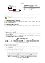
For inputs and protections see Fig.5.
-
Protection against dry operation: the panel has an input for protection against dry operation, signalled by
a float immersed in the tank of the pumps controlled by the panel. The device must be connected to the S
contact of the NGPANEL, and positioned in the tank at a level that ensures that the pumps are not damaged
by dry operation (see the installation and operating instructions of the pumps used).
-
Motor thermal protection: the device has an input for the thermal protection of each motor. If the motor used
is provided with thermal protection, this protection can be connected to the terminals KK. If the protection is
not present in the motor, the terminals must be jumpered. The terminals can be seen in Fig.1.
6.5
Connection of the alarm outputs
If alarms occur, this is indicated by the NGPANEL in three ways:
-
By the buzzer which can be activated and deactivated from the control panel, see chapter 8.4 Optional
-
By the outputs OUT1, OUT2, OUT3 which short-circuit. The alarm operating logic is the following: OUT1
closes following malfunctions of pump 1, OUT2 of pump 2 and OUT3 for general errors.
-
The alarm log can also be viewed via the indications on the display.
If the panel is not fed, OUT1, OUT2 and OUT3 are closed, so they give an alarm signal.
6.6
Connection of floats or level probes
2 or 3 control inputs can be used which must be connected as follows:
-
System with 2 floats: in this case inputs B and C are used (A must not be used, and must be jumpered in
the case of normally closed floats). The floats in the tank must be positioned as in Fig.4. For electrical
installation, see Fig.5.
-
System with 2 level probes: in this case inputs B and C are used (A must not be jumpered). The level
probes in the tank must be positioned as in Fig.4. For electrical installation, see Fig.5.
-
System with 3 floats or level probes: in this case inputs A, B and C are used. The floats or level probes
must be positioned as in Fig.4: For electrical installation, see Fig.5.

