Da-Lite ViewShare Tensioned Advantage Electrol... Instruction Book Download Page 4

4

Pre-Installation of ViewShare Screen and Roller Assembly

1.  Remove existing motor and pin end roller assembly brackets 

from inside the case.


NOTE:

 At this point the inside of case will be empty except for 

the junction box connections on the motor end.

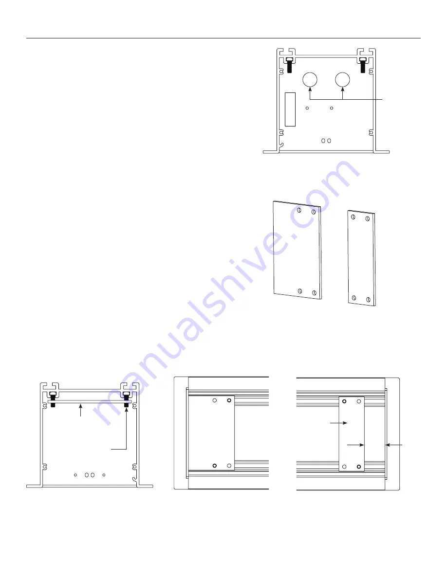
2.  Remove a single circular knockout from motor end of case for 

CAT5 cable needed in the Installation of ViewShare Screen and 
Roller Assembly (Figure 4).

 NOTE:

 The CAT5 cable should be run from the Local CAT5 to 

USB Extender in Camera and Speakerphone Installation to this 
location. Final connection of this CAT5 cable running through the 
knockout will occur in Step 10 of Installation of ViewShare Screen 
and Roller Assembly.

3.  Place the two spacing gaskets (shown in Figure 5) on the bracket 

bolts with 1/4” – ½” of the bolts showing through the bottom 
(Figure 6).

4.  Slide the motor end spacing gasket until it makes contact with 

the end of the case (Figure 7).

5.  Slide the pin end spacing gasket until it is approximately 1 ½ 

inches from the end of the case (Figure 8).

6.  Carefully unpack the new ViewShare screen and roller assembly 

and set aside. Be sure to leave the packing paper on the roller.

NOTE:

 If your screen and roller assembly was ordered with a 

new motor, please proceed to “Installation of ViewShare Screen 
and Roller Assembly”. If you are utilizing your existing motor, 
please continue to “Transfer of Existing Motor”.

Figure 4

Figure 5 – Spacing Gaskets

Figure 6

Figure 7

Figure 8

Circular
Knockouts 
for CAT5 
Cable

Spacing 

Gasket

1/4" to 1/2" of 

bolt showing

Motor End 

Gasket

Motor End 

Spacing

Gasket

Pin End 

Spacing

Gasket

1 ½ in.

Pin End 

Gasket

Summary of Contents for ViewShare Tensioned Advantage Electrol...

Page 1: ...INSTRUCTION BOOK FOR ViewShare Tensioned Advantage Electrol Retrofit...

Page 2: ...work is required Incorrect reassembly can cause electric shock when the appliance is used subsequently 5 The use of an accessory attachment not recommended by the manufacturer may cause a risk of fir...

Page 3: ...ype details 4 Remove retainer clip from the motor Figure 2 NOTE Save retainer clip for use in the installation of the ViewShare screen and roller assembly 5 Loosen but do not remove four 1 4 20 nuts s...

Page 4: ...spacing gaskets shown in Figure 5 on the bracket bolts with of the bolts showing through the bottom Figure 6 4 Slide the motor end spacing gasket until it makes contact with the end of the case Figure...

Page 5: ...bly and set aside Figure 10 NOTE Try to avoid turning the rubber collar on the motor as you are pulling the motor out of the roller as this will change the limit switch settings 3 Remove the black L b...

Page 6: ...e wooden block Figure 12 7 On the ViewShare screen and roller assembly loosen but do not remove the nut on the motor end arm bracket Figure 13 8 Remove the two end bracket bolts securing the motor end...

Page 7: ...tor into the ViewShare fabric and roller assembly NOTE When transferring the existing motor into the roller be careful to avoid unintentional damage to the screen and arm assemblies 12 Re secure the s...

Page 8: ...igure 16 NOTE If you transferred your existing motor the L brackets have already been removed 3 Install ViewShare screen and roller assembly by placing the unit inside of case and secure motor end bra...

Page 9: ...See Appendix A for motor type details Figure 19 8 Carefully remove paper and tape from roller assembly DO NOT use knife or sharp object to cut tape or you will damage the screen 9 Test installation by...

Page 10: ...carefully allow the USB to CAT5 extender to hang freely Figure 20 NOTE The USB to CAT5 connection will allow the integrated ViewShare camera to interface with the other ViewShare hardware components i...

Page 11: ...1 Connect your CAT5 cable to the local CAT5 to USB extender which should be located near your computer Connect the local CAT5 to USB extender power supply at this time NOTE The CAT5 cable should only...

Page 12: ...eady to use the camera If the LED does not turn green after install your computer may need to be restarted before the camera can be used This could be a result of the type of operating system and othe...

Page 13: ...k for continuity Cut off old splice and reconnect Defective motor limit switch or capacitor Replace motor assembly NOTE Motor is a sealed assembly Capacitor burned out Replace motor assembly Screen do...

Page 14: ...erating switch in off position 3 Turn the down limit knob Figure 22 one turn clockwise Test by raising screen surface approximately two feet then lower again Repeat until desired screen surface positi...

Page 15: ...position switch to the up position Press and hold the up button to run the screen up to the desired stop position Release the button to stop the screen DO NOT PUSH THE STOP BUTTON CAUTION Adjusting th...

Page 16: ...n to step 3 for down limit adjustment or step 4 for up limit adjustment 4 To adjust the up limit switch press and hold the up tactile button until the LED on the back of the switch turns solid green T...

Page 17: ...ally aligned loosen but do not remove the adjustment nut found inside the case behind the screen and roller assembly Figure 24 3 With the adjustment nut loosened the arms can be adjusted inward and ou...

Page 18: ...18...

Page 19: ...19...

Page 20: ...ect yourself against damage or loss in transit insure the product and prepay all transportation expenses TO THE MAXIMUM EXTENT PERMITTED BY APPLICABLE LAW THIS WARRANTY IS IN LIEU OF ALL OTHER WARRANT...

Reviews: