background image

PRE-INSTALLATION

1

INSTALLATION

1. Install screen by raising unit into position between joists at one end only. Install lag screws in mounting bracket or

hang from 3/8" rods.

2. Level unit lengthwise with a carpenter’s level and plumb level. Secure opposite end.

CAUTION! Do not secure access door or seal in until screen has been secured in position and properly tested for satisfactory
operation.

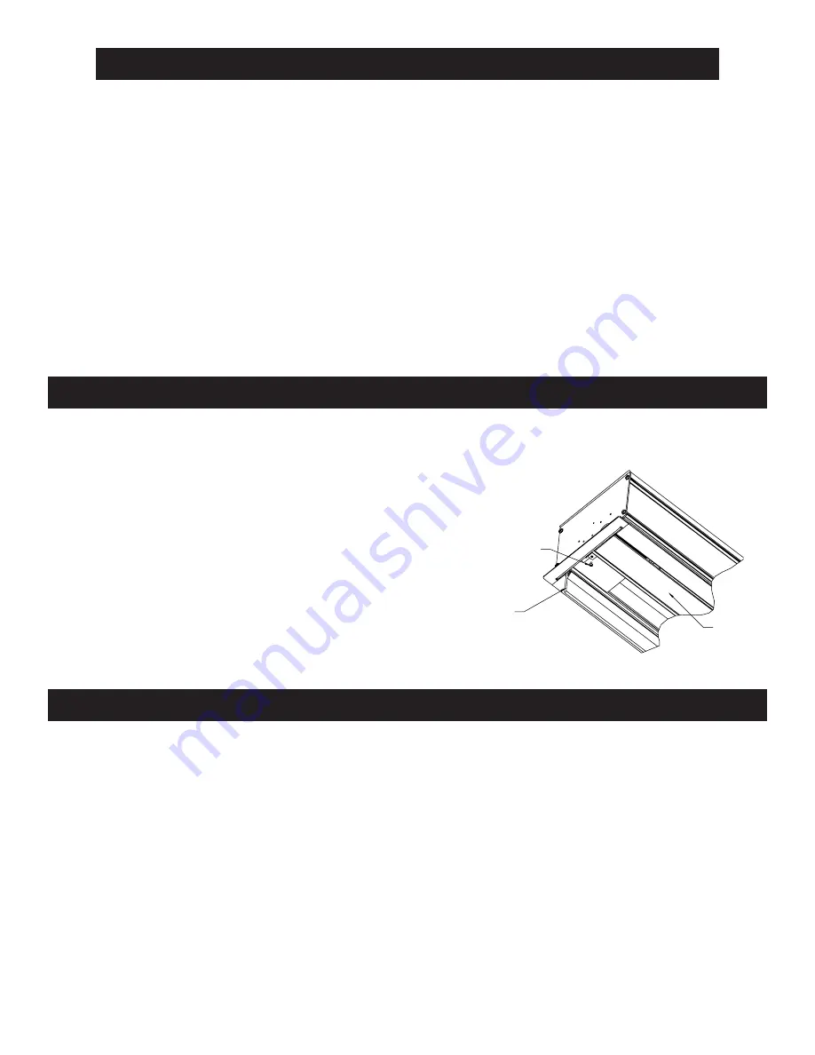
3. Remove screw at each end of roller access door (Fig. 1).

4. Remove junction box cover plate.

If your screen has the low voltage control built-in, remove access cover on right end of case.  See Figure 3.

5. Install electric hook up that applies to your unit. Make sure to review your electrical installation checklist and wiring

diagram (included) for either 120 volt switch, 220/240 volt switch, or DRC low voltage control.

NOTE: Screen has been internally wired at Da-Lite. Wiring designated “external” is completed by installer conforming to local
and national codes.

CAUTION! DO NOT CUT TAPE ON FABRIC WITH A KNIFE OR ANY SHARP TOOL. REMOVE BY HAND.

!

1. Carefully unpack screen and remove outer wrapping from case.

2. Make sure to recheck measurements of screen location before installation.

!

FABRIC DOOR

ACCESS

DOOR

SCREW FOR

SECURING ROLLER

ACCESS DOOR

FIGURE 1

IMPORTANT SAFETY INSTRUCTIONS

When using your video equipment, basic safety precautions should always be followed, including the
following:

1. Read and understand all instructions before using.

2. Position the cord so that it will not be tripped over, pulled, or contact hot surfaces.

3. If an extension cord is necessary, a cord with a current rating at least equal to that of the appliance

should be used. Cords rated for less amperage than the appliance may overheat.

4. To reduce the risk of electric shock, do not disassemble this appliance. Contact an authorized

service dealer when repair work is required. Incorrect reassembly can cause electric shock when
the appliance is used subsequently.

5. The use of an accessory attachment not recommended by the manufacturer may cause a risk of

fire, electric shock, or injury to persons.

SAVE THESE INSTRUCTIONS

Summary of Contents for TENSIONED DIRECTOR ELECTROL

Page 1: ...th Detroit Street Post Office Box 137 Warsaw Indiana 46581 0137 Phone 574 267 8101 800 622 3737 Fax 574 267 7804 www da lite com e mail info da lite com POWER PRESENTATION PRODUCTS The In Instruction Book for TENSIONED DIRECTOR ELECTROL ...

Page 2: ... codes CAUTION DO NOT CUT TAPE ON FABRIC WITH A KNIFE OR ANY SHARP TOOL REMOVE BY HAND 1 Carefully unpack screen and remove outer wrapping from case 2 Make sure to recheck measurements of screen location before installation FABRIC DOOR ACCESS DOOR SCREW FOR SECURING ROLLER ACCESS DOOR FIGURE 1 IMPORTANT SAFETY INSTRUCTIONS When using your video equipment basic safety precautions should always be f...

Page 3: ...Slat should move freely Fig 2 CAUTION Remove shipping brackets before operating screen 7 Test installation by carefully running picture surface up and down several times Be prepared to stop screen NOTE When rolled down the picture surface should wrap fully around the roller No part of the roller should be exposed Picture surface will automatically stop in the down position 8 Run the picture surfac...

Page 4: ...AM WITH ONBOARD LVC BLACK WHITE RED UP BLACK DOWN WHITE PURPLE GREEN DOOR SWITCH SCREEN MOTOR BLACK WHITE BLACK AND YELLOW LOW VOLTAGE WALL SWITCH UP STOP DOWN PUSH BUTTON SWITCHES RED BLACK WHITE 5A 125 VAC OPTIONAL INFRARED REMOTE CONNECTOR OPTIONAL RADIO FREQUENCY REMOTE CONNECTOR LVC BOARD WHITE COMMON BLACK HOT GROUND BLACK DOWN RED UP WHITE COMMON 120VAC 60HZ INPUT DOOR MOTOR BLACK CLOSE WHI...

Page 5: ... MOTOR BROWN BLUE BROWN YELLOW BROWN GREEN BLACK UP BROWN DOWN BLUE PURPLE RELAY BLUE BLACK TO JUNCTION BOX MOUNTED IN SCREEN CASE IN WHICH INTERNAL WIRING TERMINATES IN BLUE BROWN AND BLACK OPERATING SWITCH SWITCH BOX AND PLATE FURNISHED WITH SCREEN NOTE A SINGLE SWITCH CANNOT BE USED TO OPERATE MORE THAN ONE SCREEN CONTACT THE FACTORY FOR FURTHER INFORMATION IN MULTIPLE CONTROL INSTALLATIONS THE...

Page 6: ...INSTALLATION 9 1 4 3 8 THREADED ROD NOT INCLUDED ATTACHED TO MOUNTING BRACKET FINISHED CEILING SELF TRIMMING FLANGE 7 1 4 8 3 4 CASE LENGTH VARIABLE POSITION MOUNTING BRACKET 7 1 4 7 5 8 MOTOR END ELECTRICAL JUNCTION BOX 7 1 4 7 5 8 ...

Page 7: ...s a foreign substance on it which does not allow it to open by gravity SOLUTION a Replace facility fuse b Reset facility circuit breaker c Check above Tighten all loose wire connections Recheck wiring See installation instructions Down Position Check for power across black and white leads d Let motor cool down for 15 minutes Try again e Check for continuity f Replace motor assembly NOTE Motor is a...

Page 8: ...bject in screen rubbing on roller or fabric c Gear noise a Defective brake a Pin end slipped out of nylon bearing a Screen not installed properly b Fabric has backed up inside case c Fabric is damaged SOLUTION a Replace switch a See installation instructions a Center roller in case b Remove foreign object c Replace motor assembly a Replace motor assembly a Remove pin end mounting Realign motor in ...

Reviews: