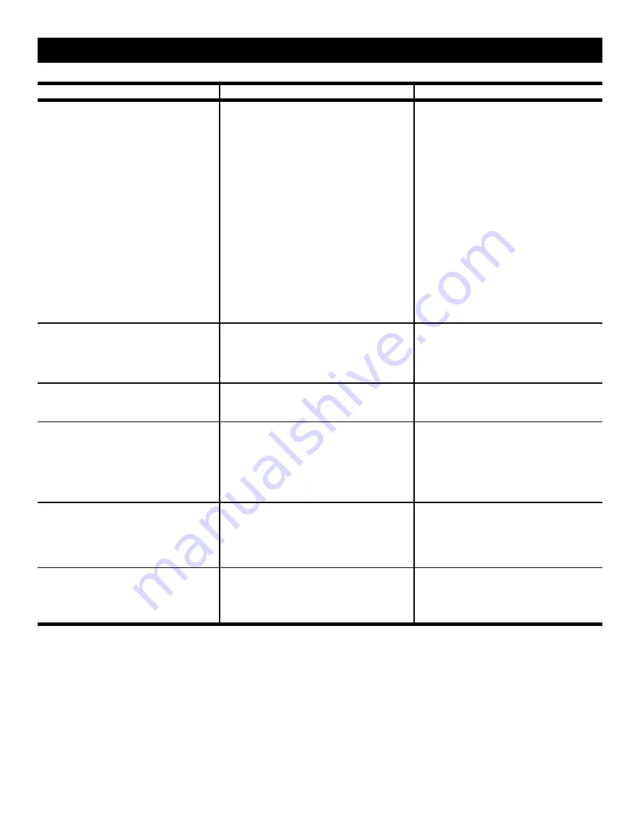
background image

6

TROUBLESHOOTING

SYMPTOM

 3.   Screen will not move 

“up.” 


Motor does

 not 

hum.


Motor 

hums.

CAUSE

(a)   Blown fuse or tripped circuit 

breaker.

(b)   No power between red and white 

leads in junction box.

(c)   Thermal overload tripped.

(d)  Burned out motor winding.


(e)  Temporary binding. 

(f)  Burned out capacitor.
(g)   Broken wire or loose connection 

in 

“up”

 position circuit.

SOLUTION

(a)   Replace fuse or reset circuit 

breaker.

(b)   Correct improper wiring. 

(c)   Let motor cool for 15 minutes. Try 

again.

(d)    Check for power between red 

and white motor leads. Replace 

motor if there is power.

(e)   With power 

off,

 turn roller by 

hand to free binding.

(f)   Replace capacitor.
(g)   Secure connection or replace 

wire.

 4.   Scraping or grinding noise.

(a)   If metal shipping bracket is left at-

tached to screen, it may be rub-

bing on motor end of roller.

(a)   Remove shipping bracket.

 6.   Fabric rubbing.

(a)   Normal condition.


NOTE: Screens with ironing boards 
have fabric that drags across the 
board.

  7.   Incorrect stopping point in  

upward

 position.

(a)   Lost roller wrap. 

(b)  Limit switch out of adjustment.

(a)   Lift bottom edge up and over 

roller.

(b)  See installation instructions.

 8.   Incorrect stopping point in 

downward

 direction.

(a)   Lost roller wrap.
(b)  Limit switch out of adjustment.

(a)   See above.
(b)  See installation instructions.

 5.   Gear noise.

(a)   Gear may need lubrication.

(a)   Apply grease.

Summary of Contents for SENIOR ELECTROL

Page 1: ...NC 3100 North Detroit Street Post Office Box 137 Warsaw Indiana 46581 0137 Phone 574 267 8101 800 622 3737 Fax 574 267 7804 www da lite com e mail info da lite com Instruction Book for senior Electrol...

Page 2: ...type installation use the wall type hanger and ceiling adapters as shown in Fig 3 on page 3 RECESSED ABOVE CEILING Other methods of installation will no doubt suggest themselves especially in new buil...

Page 3: ...s in bottom position do not adjust for more than 3 of additional drop Roller should not be exposed LESS SCREEN DROP 1 Raise picture surface approximately two feet above desired level 2 Place operating...

Page 4: ...OF BRACKET 3 4 DIAMETER HOLES 3 8 NUT BOLT 2 27 8 27 8 2 4 33 4 3 16 7 8 91 2 33 4 43 8 MOTOR COMPARTMENT 9 1 2 REINFORCED TOP LENGTH FABRIC WIDTH 23 ALL SIZES 11 5 16 18 5 8 HINGED ACCESS PANEL FOR...

Page 5: ...CTION BOX MOUNTED IN SCREEN CASE IN WHICH INTERNAL WIRING TERMINATES IN WHITE BLACK AND RED LEADS IN MULTIPLE CONTROL INSTALLATIONS THIS SWITCH IS REPLACED BY THE LOW VOLTAGE CONTROL OPERATED FROM PUS...

Page 6: ...Position Check for power across black and white leads Up Position Check for power across red and white leads d Down Position Check for power at black and white leads Up Position Check for power at re...

Page 7: ...With power off turn roller by hand to free binding f Replace capacitor g Secure connection or replace wire 4 Scraping or grinding noise a If metal shipping bracket is left at tached to screen it may...

Page 8: ...mbly Solution a Tighten set screws located on nylon gears drives limit switch b Tighten nut between adjusting knobs Tighten lead screw of limit switch 10 Screen does not stop going up or down a Limit...

Reviews: