xStack
®
DGS-3600 Series Layer 3 Managed Gigabit Ethernet Sw itch
14
Installing the SFP Ports
The xStack
®
DGS-3600 Series switches are equipped with SFP (Small Form Factor Portable) ports, which are to be used with
fiber-optical transceiver cabling in order to uplink various other networking devices for a gigabit link that may span great
distances. These SFP ports support full-duplex transmissions, have auto-negotiation and can be used with the DEM-210 (100FX-
LC), DEM-211 (100FX-LC), DEM-310GT (1000BASE-LX), DEM-311GT (1000BASE-SX), DEM-312GT2 (1000BASE-LX),
DEM-314GT (1000BASE-LHX), DEM-315GT (1000BASE-ZX), DEM-330T/R (WDM) and DEM-331T/R (WDM) transceivers.
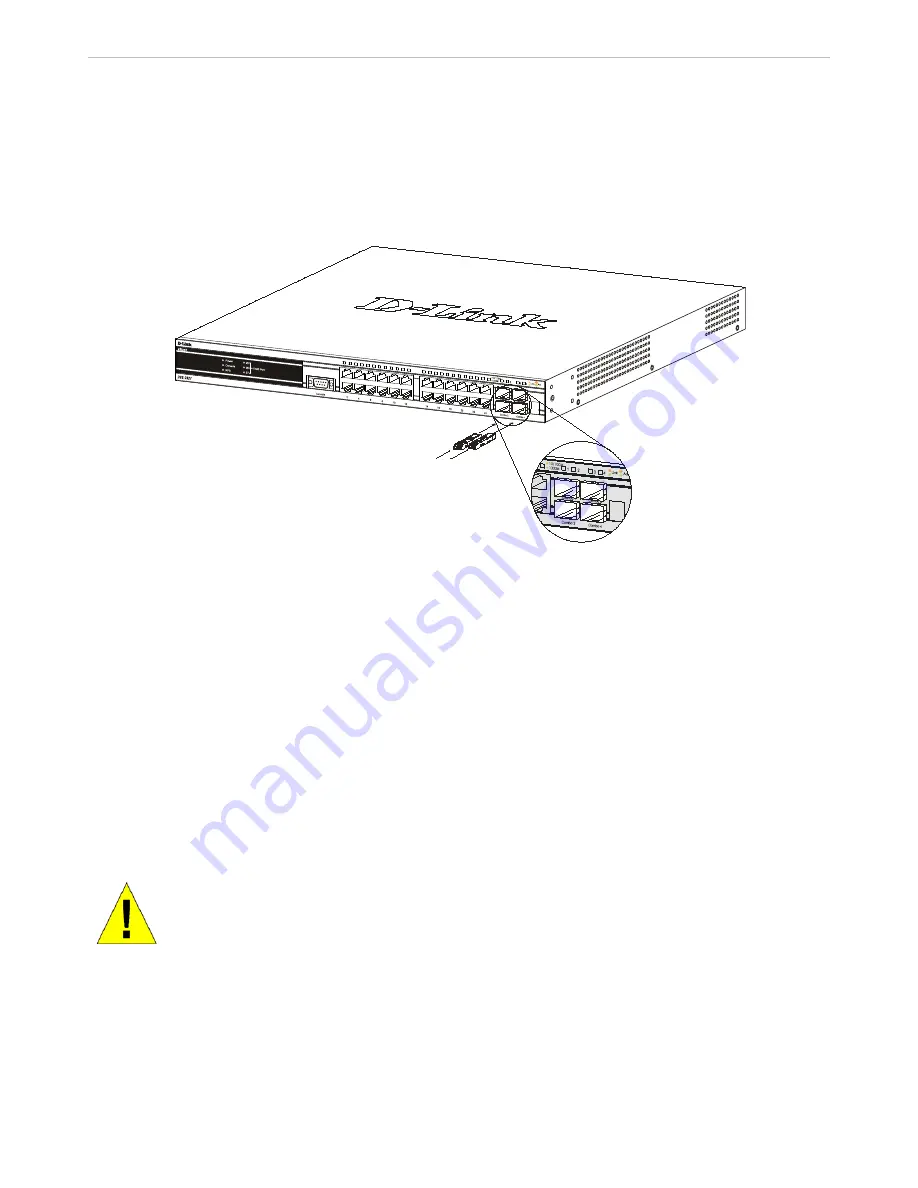
See the figure below for installing the SFP ports in the Switch.
Figure 2 - 4. Inserting the fiber-optic transceivers into the DGS-3600 Series switch
Optional 10GE Uplink Module
At the rear of the xStack
®
DGS-3600 Series switches reside optional module slots. This slot may be equipped with the DEM-
410X single-port 10GE XFP uplink module, or a DEM-410CX single-port 10GE CX4 uplink module, both sold separately.
Adding the DEM-410X optional module will allow the administrator to add a single-port 10GE stacking module which will
transmit information at a rate of ten gigabits a second. This port is compliant with standard IEEE 802.3ae, supports full-duplex
transmissions only and is to be used with XFP MSA compliant transceivers.
The DEM-410CX will transfer information at a rate of ten gigabits a second but is used as an uplink module to a network device.
Compliant with the IEEE802.3ak standard, this module will use a 4-laned copper connector to transfer information in full-duplex
mode, quickly and accurately. User beware, the cable and connector port used for this module is nearly identical to the stacking
ports and cables used for stacking in the xStack
®
Series, but can in no way be interchangeable.
To install these modules, follow the simple steps listed below.
CAUTION
: Before adding the optional module, make sure to disconnect all power sources
connected to the Switch. Failure to do so may result in an electrical shock, which may cause
damage, not only to the individual but to the Switch as well.
At the back of the Switch to the left is the slot for the optional module, as shown in Figure 1-18 and Figure 1-19. This slot should
be covered with a faceplate that can be easily removed by loosening the screws and pulling off the plate.


