background image

D-Link GO-SW-5G/8G 5/8-port Gigabit Easy Desktop Switch


vi 


When connecting or disconnecting power to hot-pluggable power supplies, if offered with your system, observe 
the following guidelines: 
– Install the power supply before connecting the power cable to the power supply. 
– Unplug the power cable before removing the power supply. 
– If the system has multiple sources of power, disconnect power from the system by unplugging all


power cables    

from the power supplies. 


Move products with care; ensure that all casters and/or stabilizers are firmly connected to the system. Avoid 
sudden stops and uneven surfaces. 


General Precautions for Rack-Mountable Products 

Observe the following precautions for rack stability and safety. Also refer to the rack installation documentation 
accompanying the system and the rack for specific caution statements and procedures. 
Systems are considered to be components in a rack. Thus, "component" refers to any system as well as to various 
peripherals or supporting hardware. 


CAUTION:

 Installing systems in a rack without the front and side stabilizers installed could cause 

the rack to tip over, potentially resulting in bodily injury under certain circumstances. Therefore, 
always install the stabilizers before installing components in the rack.  

After installing system/components in a rack, never pull more than one component out of the 
rack on its slide assemblies at one time. The weight of more than one extended component 
could cause the rack to tip over and may result in serious injury. 


Before working on the rack, make sure that the stabilizers are secured to the rack, extended to the floor, and that 
the full weight of the rack rests on the floor. Install front and side stabilizers on a single rack or front stabilizers 
for joined multiple racks before working on the rack.


Always load the rack from the bottom up, and load the heaviest item in the rack first. 


Make sure that the rack is level and stable before extending a component from the rack. 


Use caution when pressing the component rail release latches and sliding a component into or out of a rack; the 
slide rails can pinch your fingers. 


After a component is inserted into the rack, carefully extend the rail into a locking position, and then slide the 
component into the rack. 


Do not overload the AC supply branch circuit that provides power to the rack. The total rack load should not 
exceed 80 percent of the branch circuit rating. 


Ensure that proper airflow is provided to components in the rack. 


Do not step on or stand on any component when servicing other components in a rack. 


NOTE:

 A qualified electrician must perform all connections to DC power and to safety grounds. 

All electrical wiring must comply with applicable local or national codes and practices. 


CAUTION:


Never defeat the ground conductor or operate the equipment in the absence of a 

suitably installed ground conductor. Contact the appropriate electrical inspection authority or an 
electrician if you are uncertain that suitable grounding is available. 


CAUTION:


The system chassis must be positively grounded to the rack cabinet frame. Do not 

attempt to connect power to the system until grounding cables are connected. Completed power 
and safety ground wiring must be inspected by a qualified electrical inspector. An energy hazard 
will exist if the safety ground cable is omitted or disconnected. 

Summary of Contents for GO-SW-5G

Page 1: ...GO SW 5G 8G 5 8 port Gigabit Easy Desktop Switch Manual RECYCLABLE V2 10 ...

Page 2: ...This is a Class B product In a domestic environment this product may cause radio interference in which case the user may be required to take adequate measures Warnung Dies ist ein Produkt der Klasse B Im Wohnbereich kann dieses Produkt Funkstoerungen verursachen In diesem Fall kann vom Benutzer verlangt werden angemessene Massnahmen zu ergreifen Precaución Este es un producto de Clase B En un ento...

Page 3: ...HNOLOGY 1 SWITCHING TECHNOLOGY 2 SWITCH DESCRIPTION 2 Features 2 FRONT PANEL COMPONENTS 3 LED Indicators 4 REAR PANEL DESCRIPTION 5 INSTALLATION 6 Package Contents 6 BEFORE YOU CONNECT TO THE NETWORK 6 POWER ON 7 Power Failure 7 CONNECTING THE SWITCH 8 SWITCH TO END NODE 8 SWITCH TO HUB OR SWITCH 8 CONNECTING TO NETWORK BACKBONE OR SERVER 9 TECHNICAL SPECIFICATIONS 10 GLOSSARY 12 ...

Page 4: ...Switch to an end node hub Switch or backbone server Appendix A Technical Specifications The technical specifications of the GO SW 5G GO SW 8G Glossary Lists definitions for terms and acronyms used in this document Intended Readers The GO SW 5G GO SW 8G Manual contains information for setup and management and of the GO SW 5G GO SW 8G Switch This manual is intended for network managers familiar with...

Page 5: ...f power source required consult your service provider or local power company To help avoid damaging your system be sure the voltage selection switch if provided on the power supply is set to match the power available at your location 115 volts V 60 hertz Hz in most of North and South America and some Far Eastern countries such as South Korea and Taiwan 100 V 50 Hz in eastern Japan and 100 V 60 Hz ...

Page 6: ...are secured to the rack extended to the floor and that the full weight of the rack rests on the floor Install front and side stabilizers on a single rack or front stabilizers for joined multiple racks before working on the rack Always load the rack from the bottom up and load the heaviest item in the rack first Make sure that the rack is level and stable before extending a component from the rack ...

Page 7: ...ake the following steps to prevent damage from electrostatic discharge ESD 1 When unpacking a static sensitive component from its shipping carton do not remove the component from the antistatic packing material until you are ready to install the component in your system Just before unwrapping the antistatic packaging be sure to discharge static electricity from your body 2 When transporting a sens...

Page 8: ...ttlenecks that frequently develop as computers and their busses get faster and more users use applications that generate more traffic Upgrading key components such as your backbone and servers to Gigabit Ethernet can greatly improve network response times as well as significantly speed up the traffic between your subnetworks Gigabit Ethernet enables fast optical fiber connections to support video ...

Page 9: ...can be used to split parts of the network into different collision domains for example making it possible to expand your Fast Ethernet network beyond the 205 meter network diameter limit for 100BASE TX networks Switches supporting both traditional 10Mbps Ethernet and 100Mbps Fast Ethernet are also ideal for bridging between existing 10Mbps networks and new 100Mbps networks Switching LAN technology...

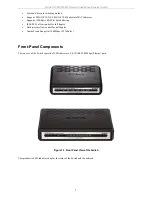
Page 10: ...r data buffering IEEE 802 3x flow control for full duplex Back pressure flow control for half duplex Jumbo Frame Support at 1000Mbps 9216Bytes Front Panel Components The top case of the Switch consists of LED indicators 5 8 10 100 1000 Mbps Ethernet ports Figure 1 1 Front Panel View of the Switch Comprehensive LED indicators display the status of the Switch and the network ...

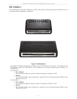
Page 11: ...Indicators The LED indicators of the Switch include Power and Link Act as described below For GO SW 5G Power Indicator This green indicator light is on when the Switch is receiving power otherwise it is off Link Act This LED indicator light is green when the port is connected to a device The green indicator blinks as data is transmitted or received For GO SW 8G Power Indicator This green indicator...

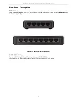
Page 12: ... power adapter Check the technical specification section for information about the AC power input voltage Figure 1 3 Rear panel view of the Switch 10 100 1000BASE T Ports Five and eight 5 8 Gigabit Ethernet Auto Negotiating ports 10 100 1000Mbps Comprehensive LED indicators display the conditions of the Switch and status of the network ...

Page 13: ...l surface that can support at least 3 kg 6 6 lbs of weight Do not place heavy objects on the Switch The power outlet should be within 1 82 meters 6 feet of the Switch Visually inspect the power cord and see that it is fully secured to the AC power port Make sure that there is adequate space for proper heat dissipation from and adequate ventilation around the Switch Leave at least 10 cm 4 inches of...

Page 14: ... of the Switch and the other end into the local power source outlet After the Switch is powered on the LED indicators will momentarily blink This blinking of the LED indicators represents a reset of the system Power Failure As a precaution in the event of a power failure unplug the Switch When power is resumed plug the Switch back in ...

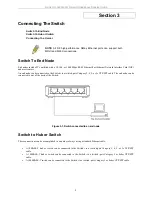
Page 15: ...e connected to any of the ports of the Switch Figure 3 1 Switch connected to an end node Switch to Hub or Switch These connections can be accomplished in a number of ways using a standard Ethernet cable A 10BASE T hub or switch can be connected to the Switch via a twisted pair Category 3 4 5 or 5e UTP STP cable A 100BASE T hub or switch can be connected to the Switch via a twisted pair Category 5 ...

Page 16: ... to a port on a hub or switch using either a straight or crossover cable any standard Ethernet cable is fine Connecting To Network Backbone or Server Any of the five Gigabit Ethernet ports are ideal for uplinking to a network backbone or network server Figure 3 3 Connection to a Server ...

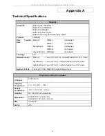
Page 17: ...lex Gigabit Ethernet 2000Mbps Full duplex Topology Star Network Cables Ethernet 2 pair UTP Cat 3 4 5 Unshield Twisted Pair UTP Cable Fast Ethernet 2 pair UTP Cat 5 Unshield Twisted Pair UTP Cable Gigabit Ethernet 4 pair UTP Cat 5 Unshield Twisted Pair UTP Cable Number of Ports Five Eight 10 100 1000BASE T Gigabit Ethernet ports Physical and Environmental DC Inputs AC DC 5V 1A Operating Temperature...

Page 18: ...tch 11 Performance Transmission Method Store and forward RAM Buffer 128KBytes per device Filtering Address Table 2K GO SW 5G 8K GO SW 8G MAC address per device Packet Filtering Forwarding Rate Full wire speed MAC Address Learning Self learning auto aging ...

Page 19: ... to all destination devices on the network broadcast storm Multiple simultaneous broadcasts that typically absorb available network bandwidth and can cause network failure console port The port on the Switch accepting a terminal or modem connector It changes the parallel arrangement of data within computers to the serial form used on data transmission links This port is most often used for dedicat...

Page 20: ...t Protocol A protocol originally designed to be used in managing TCP IP internets SNMP is presently implemented on a wide range of computers and networking equipment and may be used to manage many aspects of network and end station operation Spanning Tree Protocol STP A bridge based system for providing fault tolerance on networks STP works by allowing you to implement parallel paths for network t...

Reviews: