background image

DSL-2540U

 ADSL/Ethernet Router with Built-in Switch

User Manual

Configuring via Web-based Interface

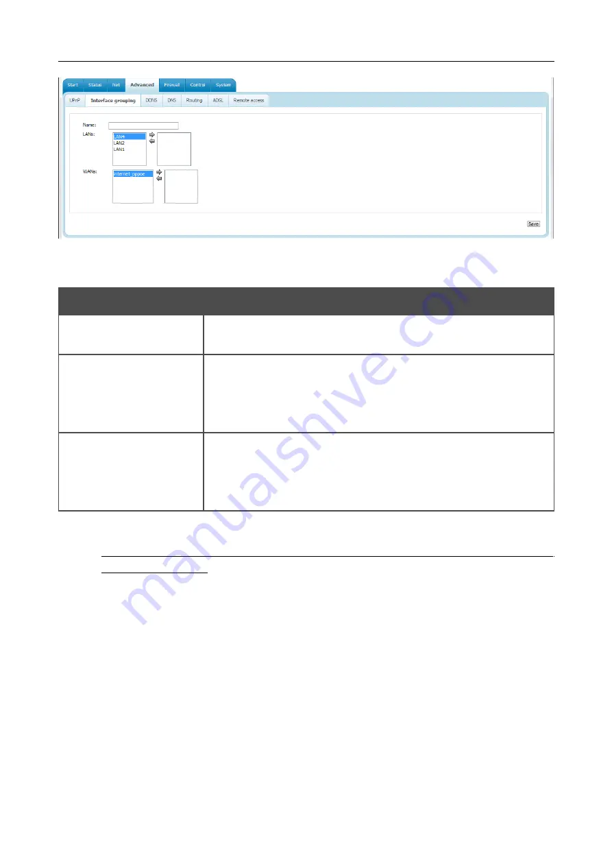
Figure 55. The page for adding a new group of ports.

You can specify the following parameters:

Parameter

Description

Name

A name for the group for easier identification. You can specify any 
name.

LANs

The   list   of   available   internal   interfaces   is   displayed   in   the   left 
column of the line.

Use the button ==> to select interfaces. The selected interfaces will 
be displayed in the right column of the field.

WANs

WAN connections to which the new group will be assigned.  

WAN 

connections of PPPoA and IPoA type cannot be added to groups

.

Use   the   button   ==>   to   select   WAN   connections.   The   selected 
connections will be displayed in the right column of the field.

Click the 

Save

 button.

!

When you add an interface to the new group, it is excluded from the group to which it has 
been assigned before.

To edit or remove an existing group, select the relevant group on the  

Advanced / Interface 

grouping

 page. On the page displayed, change the parameters and click the 

Save

 button, or click 

the  

Delete

  button.   When   you   delete   a   group,   interfaces   assigned   to   it   are   reassigned   to   the 

DEFAULT

 group.

Page 

60

 of 86

Summary of Contents for DSL-2540U

Page 1: ...User Manual DSL 2540U ADSL Ethernet Router with Built in Switch July 2012 ...

Page 2: ...t Adapter 13 Obtaining IP Address Automatically in OS Windows XP 13 Obtaining IP Address Automatically in OS Windows 7 16 Connecting to Web based Interface 21 Saving and Restoring Settings 24 Chapter 4 Configuring via Web based Interface 25 Wizards 25 Internet Setup Wizard 25 PPPoE or PPPoA Connection 26 IPoA or Static IP Connection 30 Dynamic IP Connection 33 Bridge Connection 36 Site Setup Wizar...

Page 3: ... 61 DNS 62 Routing 63 ADSL 65 Remote Access 66 Firewall 68 IP Filters 68 Virtual Servers 71 DMZ 73 Application Rules 74 MAC Filter 76 Control 78 URL Filter 78 System 80 Administrator Password 80 Configuration 81 System Log 82 Firmware Upgrade 84 NTP Client 85 Chapter 5 Abbreviations and Acronyms 86 Page 3 of 86 ...

Page 4: ...uick Installation Guide A reference to a document Change A name of a menu menu item control field checkbox drop down list button etc 192 168 1 1 Data that you should enter in the specified field Information An important note Document Structure Chapter 1 describes the purpose and structure of the document Chapter 2 gives an overview of the router s hardware and software features and describes its a...

Page 5: ...n firewall the QoS engine and numerous additional features The router is equipped with an ADSL port to connect to an ADSL line and 4 Ethernet ports to connect workstations Due to this feature DSL 2540U represents a moderate priced solution for creating wired networks without an additional switch In addition any Ethernet port of the device can be used to connect to a private Ethernet line The route...

Page 6: ...92 1 G dmt Annex A ITU T G 992 2 G lite Annex A ITU T G 994 1 G hs ADSL2 ITU T G 992 3 G dmt bis Annex A L M ITU T G 992 4 G lite bis Annex A ADSL2 ITU T G 992 5 Annex A L M WAN Connection Types ADSL PPPoE PPPoA IPoA Static IP Dynamic IP Bridge Ethernet PPPoE Static IP Dynamic IP Bridge The device features are subject to change without notice For the latest versions of the firmware and relevant do...

Page 7: ...PPP over ATM RFC 2364 PPP over Ethernet PPPoE Keep alive for PPP connections Network Protocols and Functions Static IP routing NAT Network Address Translation DHCP server client relay DNS relay DDNS UPnP Support of VLAN IGMP proxy Firewall and Access Management Functions Network Address Translation NAT Stateful Packet Inspection SPI URL filter Packet filtering IP ICMP TCP UDP Virtual servers Preve...

Page 8: ...erface for configuration and management Access via TELNET Firmware update via web based interface Saving restoring configuration to from file Support of remote logging Automatic synchronization of system time with NTP server LEDs Power Status LAN 1 4 DSL Internet Power External power adapter DC 12V 0 5A ON OFF power switch Reset to Factory Defaults button Page 8 of 86 ...

Page 9: ...green A device is connected to the port of the router for the LAN port configured as the WAN port the router is connected to an Ethernet line Blinking green The relevant LAN port is active upstream or downstream traffic DSL Solid green DSL has been synchronized Blinking green Detecting a carrier signal and synchronizing DSL No light No carrier signal Internet Solid green A WAN connection ADSL and ...

Page 10: ... line LAN 1 4 4 Ethernet ports to connect Ethernet devices One port can be used to connect to a private Ethernet line RESET A button to restore the factory default settings To restore the factory defaults push the button with the device turned on hold it for 7 10 seconds and then release the button 12V 0 5A Power connector ON OFF A button to turn the router on off Page 10 of 86 ...

Page 11: ...ons Place your router on a flat horizontal surface or mount the router on the wall the mounting holes are located on the bottom panel of the device Make sure that the router is provided with sufficient ventilation To prevent overheating do not obstruct the ventilation openings of the router Plug the router into a surge protector to reduce the risk of damage from power surges and lightning strikes ...

Page 12: ...d interface is available from any operating system that supports a web browser Web Browser The following web browsers are recommended Windows Internet Explorer Mozilla Firefox or Opera For successful operation JavaScript should be enabled on the web browser Make sure that JavaScript has not been disabled by other software such as virus protection or web user security packages running on your compu...

Page 13: ...to an Ethernet line connect the Ethernet cable between any of four Ethernet ports located on the back panel of the router and the Ethernet line 5 Connect the power cord to the power connector port on the back panel of the router then plug the power adapter into an electrical outlet or power strip 6 Turn on the router by pressing the ON OFF button on its back panel 7 Turn on your PC and wait until ...

Page 14: ...itch User Manual Installation and Connection 3 In the Local Area Connection Properties window on the General tab select the Internet Protocol TCP IP line Click the Properties button Figure 4 The Local Area Connection Properties window Page 14 of 86 ...

Page 15: ...tain an IP address automatically and Obtain DNS server address automatically radio buttons Click the OK button Figure 5 The Internet Protocol TCP IP Properties window 5 Click the ОК button in the connection properties window Now your computer is configured to obtain an IP address automatically Page 15 of 86 ...

Page 16: ...on and proceed to the Control Panel window 2 Select the Network and Sharing Center section If the Control Panel has the category view the Category value is selected from the View by drop down list in the top right corner of the window choose the View network status and tasks line under the Network and Internet section Figure 6 The Control Panel window Page 16 of 86 ...

Page 17: ...t Router with Built in Switch User Manual Installation and Connection 3 In the menu located on the left part of the window select the Change adapter settings line Figure 7 The Network and Sharing Center window Page 17 of 86 ...

Page 18: ...Built in Switch User Manual Installation and Connection 4 In the opened window right click the relevant Local Area Connection icon and select the Properties line in the menu displayed Figure 8 The Network Connections window Page 18 of 86 ...

Page 19: ...er Manual Installation and Connection 5 In the Local Area Connection Properties window on the Networking tab select the Internet Protocol Version 4 TCP IPv4 line Click the Properties button Figure 9 The Local Area Connection Properties window Page 19 of 86 ...

Page 20: ...n IP address automatically and Obtain DNS server address automatically radio buttons Click the OK button Figure 10 The Internet Protocol Version 4 TCP IPv4 Properties window 7 Click the OK button in the connection properties window Now your computer is configured to obtain an IP address automatically Page 20 of 86 ...

Page 21: ...ress the Enter key Figure 11 Connecting to the web based interface of the DSL 2540U device 3 On the opened page enter the username login and password for the administrator account by default the following username and password are specified admin admin Then click the Enter link Figure 12 The login page If the error The page cannot be displayed or Unable to display the page Could not connect to rem...

Page 22: ...t site button After clicking the button the Site Setup Wizard opens see the Site Setup Wizard section page 38 To get back to the quick settings page from any Wizard or web based interface menu section left click the D Link logo in the top left corner of the page To configure all parameters of the router independently without the Wizards click the Configure manually button After clicking the button...

Page 23: ...ing the line the e mail client window for sending a new letter to the specified address opens To edit the router s local interface parameters left click the IP or MAC address of the local interface the right column of the LAN IP line or LAN MAC line correspondingly After clicking the line the page for editing the LAN interface opens see the LAN section page 56 The web based interface of the router...

Page 24: ...n save the device s parameters via the Save button on the System Configuration page Click the Backup line and follow the dialog box appeared to save the configuration all settings of the router to your PC Also you can save the router s configuration to your PC via the Backup button on the System Configuration page Click the Factory line to restore the factory default settings Also you can restore ...

Page 25: ...t Setup Wizard To configure connection to the Internet click the Connect to internet button Figure 18 Configuring connection to the Internet To create a new WAN connection click the add new connection link Figure 19 The page for selecting the connection type On the opened page select the needed choice of the radio button and click the Next button Page 25 of 86 ...

Page 26: ...ntification and click the Next button Figure 21 Configuring PPPoE WAN connection In the VPI field specify the VPI In the VCI field specify the VCI From the Encapsulation Mode drop down list select a method of encapsulation In the Username field enter your login and in the Password and Password confirmation fields the password provided by your ISP If authorization is not required select the Without...

Page 27: ...PoA WAN connection Figure 22 Configuring PPPoE WAN connection Parameter Description Service name Displayed for the PPPoE type only The name of the PPPoE authentication server Authentication algorithm Select a required authentication method from the drop down list or leave the AUTO value MTU The maximum size of units transmitted by the interface Page 27 of 86 ...

Page 28: ... should be terminated PPP IP extension This option is used by some ISPs Contact your ISP to clarify if this checkbox needs to be enabled Use Static IP Address Select the checkbox if you want to use a static IP address to access the Internet In the Static IP Address field displayed when the checkbox is selected specify a static IP address PPP debug Select the checkbox if you want to log all data on...

Page 29: ...pe only Figure 24 Configuring PPPoE WAN connection Parameter Description Allow to create several connections assigned to this port Select the checkbox to allow the router to use several untagged connections Use VLAN Select the checkbox to allow the router to use tagged VLAN connections VLAN ID An identifier for the VLAN The field is displayed when the Use VLAN checkbox is selected VLAN priority A ...

Page 30: ...for the connection for easier identification and click the Next button Figure 26 Configuring Static IP WAN connection In the VPI field specify the VPI In the VCI field specify the VCI From the Encapsulation Mode drop down list select a method of encapsulation Fill in the IP address and Netmask fields In the Gateway IP address field enter the IP address of the gateway used by this WAN connection Pa...

Page 31: ...ast Select the checkbox to allow multicast traffic from the external network e g video streaming to be received NAT Select the checkbox if you want one WAN IP address to be used for all computers of your LAN Firewall Select the checkbox to enable protection against ARP and DDoS attacks Click the Next button to continue If needed change the connection settings available in the VLAN section the page...

Page 32: ...se tagged VLAN connections VLAN ID An identifier for the VLAN The field is displayed when the Use VLAN checkbox is selected VLAN priority A priority tag for the type of traffic transmitted The field is displayed when the Use VLAN checkbox is selected Click the Next button to continue After that the page displaying all specified settings opens Click the Save button to create the connection or the B...

Page 33: ...d specify a name for the connection for easier identification and click the Next button Figure 30 Configuring Dynamic IP WAN connection In the VPI specify the VPI In the VCI field specify the VCI From the Encapsulation Mode drop down list select a method of encapsulation If your ISP has provided its identifier fill in the Vendor ID field Click the Next button to continue Page 33 of 86 ...

Page 34: ...P Multicast Select the checkbox to allow multicast traffic from the external network e g video streaming to be received NAT Select the checkbox if you want one WAN IP address to be used for all computers of your LAN Firewall Select the checkbox to enable protection against ARP and DDoS attacks Click the Next button to continue If needed change the connection settings available in the VLAN section ...

Page 35: ...se tagged VLAN connections VLAN ID An identifier for the VLAN The field is displayed when the Use VLAN checkbox is selected VLAN priority A priority tag for the type of traffic transmitted The field is displayed when the Use VLAN checkbox is selected Click the Next button to continue After that the page displaying all specified settings opens Click the Save button to create the connection or the B...

Page 36: ...N connection In the Name field specify a name for the connection for easier identification and click the Next button Figure 34 Configuring Bridge WAN connection In the VPI field specify the VPI In the VCI field specify the VCI From the Encapsulation Mode drop down list select a method of encapsulation Click the Next button to continue Page 36 of 86 ...

Page 37: ...ons Use VLAN Select the checkbox to allow the router to use tagged VLAN connections VLAN ID An identifier for the VLAN The field is displayed when the Use VLAN checkbox is selected VLAN priority A priority tag for the type of traffic transmitted The field is displayed when the Use VLAN checkbox is selected Click the Next button to continue After that the page displaying all specified settings open...

Page 38: ...virtual server for easier identification You can specify any name Interface Select a WAN connection to which this virtual server will be assigned Private IP Enter the IP address of the server from the local area network To choose a device connected to the router s LAN at the moment select the relevant value from the drop down list located to the right of the Private IP field the field will be fill...

Page 39: ...e router s network and its web based interface Network Statistics On the Status Network statistics page you can view statistics for all interfaces connections existing in the system For each connection the following data are displayed state IP address subnet mask and gateway if the connection is established MAC address MTU value and volume of data received and transmitted with increase of the volu...

Page 40: ...Switch User Manual Configuring via Web based Interface DSL Status The information shown on the tabs of the Status DSL status page can be used for troubleshooting and diagnosing connection problems Figure 38 The Status DSL status page Page 40 of 86 ...

Page 41: ... ADSL Ethernet Router with Built in Switch User Manual Configuring via Web based Interface WAN Status The Status WAN status page displays active WAN connections Figure 39 The Status WAN status page Page 41 of 86 ...

Page 42: ...terface DHCP The Status DHCP page displays the information on computers that have been identified by hostnames and MAC addresses and have got IP addresses from the DHCP server of the device as well as the IP address expiration periods the lease time Figure 40 The Status DHCP page Page 42 of 86 ...

Page 43: ... Manual Configuring via Web based Interface Routing Table The Status Routing table page displays the information on routes The table contains destination IP addresses gateways subnet masks and other data Figure 41 The Status Routing table page Page 43 of 86 ...

Page 44: ...a on network devices connected to the router The page displays devices connected to the built in switch of the router and devices accessing the web based interface of the router Figure 42 The Status LAN clients page For each device the following data are displayed the IP address the MAC address and the interface to which the device is connected Page 44 of 86 ...

Page 45: ...page To create a new connection click the Add button On the page displayed specify the relevant values To edit an existing connection left click the relevant line in the table On the page displayed change the parameters and click the Save button To delete an existing connection left click the relevant line in the table On the page displayed click the Delete button To use one of existing WAN connec...

Page 46: ...thernet Router with Built in Switch User Manual Configuring via Web based Interface Creating ADSL WAN Connection Figure 44 The page for creating a new connection The General settings ATM and VLAN sections Page 46 of 86 ...

Page 47: ... is from 0 to 250 VCI Virtual Circuit Identifier The valid range is from 32 to 65535 Encapsulation Mode Select LLC or VC from the drop down list QoS A class of traffic for this connection UBR Unspecified Bit Rate The UBR service is used for applications that allow various delays and losses of packets It is appropriate to use the UBR service for text data image transfer applications as well as mess...

Page 48: ...e field is displayed Specify a required value in cells per second Non Realtime VBR Non Real time Variable Bit Rate This service can be used for transferring data that have critical response time requirements e g air ticket booking bank transactions and process monitoring When you select this value from the drop down list the Peak Cell Rate Sustainable Cell Rate and Maximum Burst Size fields are di...

Page 49: ...splayed when the Use VLAN checkbox is selected VLAN priority A priority tag for the type of traffic transmitted The field is displayed when the Use VLAN checkbox is selected The Miscellaneous section is displayed for all connection types except for Bridge Figure 45 The page for creating a new connection The Miscellaneous section Parameter Description Miscellaneous Enable IGMP Multicast Select the ...

Page 50: ... access the Internet Password confirmation The confirmation of the entered password to avoid mistypes Service name Displayed for the PPPoE type only The name of the PPPoE authentication server Authentication algorithm Select a required authentication method from the drop down list or leave the AUTO value MTU The maximum size of units transmitted by the interface Keep Alive Select the checkbox if y...

Page 51: ...o log all data on PPP connection debugging PPPoE pass through Displayed for the PPPoE type only Select the checkbox if you want to allow PPPoE clients of computers from your LAN to connect to the Internet through this PPPoE connection of the router The IP section is displayed for the Static IP Dynamic IP and IPoA connection types Figure 47 The page for creating a new connection The IP section Para...

Page 52: ...ings and Ethernet sections Parameter Description General settings Connection Type A type of network protocol to be used by the connection Available values PPPoE Static IP Dynamic IP Bridge Port Select the value corresponding to the LAN port specified as the WAN port Name A name for connection for easier identification Enable Select the checkbox to enable the connection Direction The direction of t...

Page 53: ... identifier for the VLAN The field is displayed when the Use VLAN checkbox is selected VLAN priority A priority tag for the type of traffic transmitted The field is displayed when the Use VLAN checkbox is selected The Miscellaneous section is displayed for all connection types except for Bridge Figure 49 The page for creating a new connection The Miscellaneous section Parameter Description Miscell...

Page 54: ...password to access the Internet Password confirmation The confirmation of the entered password to avoid mistypes Service name The name of the PPPoE authentication server Authentication algorithm Select a required authentication method from the drop down list or leave the AUTO value MTU The maximum size of units transmitted by the interface Keep Alive Select the checkbox if you want the router to k...

Page 55: ... Select the checkbox if you want to log all data on PPP connection debugging PPPoE pass through Select the checkbox if you want to allow PPPoE clients of computers from your LAN to connect to the Internet through this PPPoE connection of the router The IP section is displayed for the Static IP and Dynamic IP connection types Figure 51 The page for creating a new connection The IP section Parameter...

Page 56: ... address and IP address pairs set a fixed IP address in the local area network for a device with a certain MAC address The router assigns IP addresses in accordance with the specified pairs only when the DHCP server is enabled in the DHCP server section in the Mode drop down list the Enable value is selected To create a MAC IP pair click the Add button and specify the following parameters Paramete...

Page 57: ...er is used to assign IP addresses to clients When this value is selected the External DHCP server IP field is displayed on the page Start IP The start IP address of the address pool used by the DHCP server to distribute IP addresses to clients End IP The end IP address of the address pool used by the DHCP server to distribute IP addresses to clients Lease time The lifetime of IP addresses leased b...

Page 58: ...ed interface UPnP On the Advanced UPnP page you can enable and disable the UPnP function UPnP is a set of networking protocols designed for automatic configuration of network devices The UPnP function performs automatic configuration of the device s parameters for network applications requiring an incoming connection to the router Figure 53 The Advanced UPnP page If you want to enable the UPnP fun...

Page 59: ...le virtual ports for the Ethernet switch select the Enable virtual ports checkbox Figure 54 The Advanced Interface grouping page To enable the Ethernet WAN function follow the steps below 1 Select the choice corresponding to the LAN port that will be used as the WAN port of the Ethernet WAN port radio button 2 Select the needed choice of the Ethernet WAN type radio button Single service over one c...

Page 60: ... the field WANs WAN connections to which the new group will be assigned WAN connections of PPPoA and IPoA type cannot be added to groups Use the button to select WAN connections The selected connections will be displayed in the right column of the field Click the Save button When you add an interface to the new group it is excluded from the group to which it has been assigned before To edit or rem...

Page 61: ...DNS Service Select a DDNS provider from the drop down list Host name The domain name registered at your DDNS provider User name The username to authorize for your DDNS provider User password The password to authorize for your DDNS provider Interface Select a WAN connection which IP address will be used to access the DDNS service Click the Change button To edit parameters of the existing DDNS servi...

Page 62: ...tomatically from your ISP upon installing a connection When you use the built in DHCP server the network parameters including DNS servers are distributed to clients automatically If you want to configure automatic obtainment of DNS servers addresses deselect the Manual checkbox select a WAN connection which will be used to obtain addresses of DNS servers automatically from the Interface drop down ...

Page 63: ...anced Routing page you can add static routes routes for networks that are not connected directly to the device but are available through the interfaces of the device into the system Figure 59 The Advanced Routing page To create a new route click the Add button Figure 60 The page for adding a static route Page 63 of 86 ...

Page 64: ... through which the destination network can be accessed from the drop down list If you have selected the Auto value of this drop down list the router itself sets the interface on the basis of data on connected networks Click the Save button To edit an existing route select the needed route in the table On the opened page change the needed parameters and click the Save button To remove an existing r...

Page 65: ...guring via Web based Interface ADSL The Advanced ADSL page includes the set of ADSL standards that should be defined by an ISP Contact your ISP to set proper parameters Select the relevant options and click the Change button Figure 61 The Advanced ADSL page Page 65 of 86 ...

Page 66: ...fy the following parameters Parameter Description Name A name for the rule for easier identification You can specify any name Interface A physical interface through which the web based interface of the router is accessed IP address A host or a subnet to which the rule is applied To choose a device connected to the router s LAN at the moment select the relevant value from the drop down list located...

Page 67: ...ased Interface Click the Change button To edit a rule for remote access click the relevant link On the opened page change the needed parameters and click the Change button To remove a rule for remote access click the relevant link On the opened page click the Delete button Page 67 of 86 ...

Page 68: ...he router add rules for IP filtering create virtual servers define a DMZ configure the Port Triggering function configure the MAC filter IP Filters On the Firewall IP filters page you can create new rules for filtering IP packets and edit or remove existing rules Figure 64 The Firewall IP filters page To create a new rule click the Add button Page 68 of 86 ...

Page 69: ...ssion Select a value from the drop down list To apply the rule to all protocols from the list select the All value when this value is selected the Ports section is not displayed Action Select an action for the rule ACCEPT Allows packet transmission in accordance with the criteria specified by the rule DROP Denies packet transmission in accordance with the criteria specified by the rule IP Addresse...

Page 70: ...ination first field and the ending IP address in the Destination last field If the IP address range checkbox is not selected specify the starting IP address of the host or subnet in the Destination field To specify an IP address add 32 To choose a device connected to the router s LAN at the moment select the relevant IP address from the drop down list located to the right of the field the field wi...

Page 71: ...r click the Add button Figure 67 The page for adding a virtual server You can specify the following parameters Parameter Description Template Select a virtual server template from the drop down list or select Custom to specify all parameters of the new virtual server manually Name A name for the virtual server for easier identification You can specify any name Interface A WAN connection to which t...

Page 72: ...nd the end value for the port range If you need to specify one port enter the needed value in the Private port begin field and leave the Private port end field blank Private IP The IP address of the server from the local area network To choose a device connected to the router s LAN at the moment select the relevant value from the drop down list located to the right of the Private IP field the fiel...

Page 73: ...e relevant value from the drop down list located to the right of the field the field will be filled in automatically and click the Change button Note that when the DMZ is enabled all traffic coming to a port of the WAN interface of the router is directed to the same port of the specified IP address Also note that virtual servers have higher priority than the DMZ host In other words if there has be...

Page 74: ...cation Rules On the Firewall Application rules page you can define rules for the Port Triggering function Figure 69 The Firewall Application rules page To add a new rule for the Port Triggering function click the Add button Figure 70 The page for adding a rule for the Port Triggering function Page 74 of 86 ...

Page 75: ...e needed value in the Starting port field and leave the Ending port field blank Outgoing port and protocol settings Protocol A protocol to which this rule will be applied upon transferring data from the specified port or port range Starting port Ending port A range of the router s ports from which data are transferred to the external network outgoing traffic Specify the start and the end value for...

Page 76: ...he Configuration tab you can select the operating mode of the MAC filter Select the Allow value from the Action drop down list to allow traffic affected by the rules from the MAC addresses tab and block the other traffic Select the Deny value from the drop down list to block only traffic affected by the rules from the MAC addresses tab Figure 71 The Firewall MAC filter page The Configuration tab T...

Page 77: ...d to the router s LAN at the moment select the relevant value from the drop down list located to the right of the field the field will be filled in automatically Direction Select a direction for which the rule will be applied Protocol Select a protocol for which the rule will be applied The Any value means any protocol from those displayed in the list Interface Select a WAN connection with the Bri...

Page 78: ...n tab then select a needed mode from the URL filter type drop down list Block listed URLs when this value is selected the router blocks access to all addresses specified on the URL addresses tab Block all URLs except listed when this value is selected the router allows access to addresses specified on the URL addresses tab and blocks access to all other web sites Click the Change button To specify...

Page 79: ...L address field specify a port as usual you need to specify port 80 for HTTP then click the Save button To remove an address from the list of URL addresses select the relevant address in the table on the URL addresses tab and click the Delete button To disable the URL filter deselect the Enable Disable URL filter checkbox on the Configuration tab then click the Change button Page 79 of 86 ...

Page 80: ...gs view the system log update the firmware of the router configure automatic synchronization of the system time Administrator Password On the System Administrator password page you can change the password for the administrator account used to access the web based interface of the router and to access the device via TELNET For security reasons it is strongly recommended to change the administrator ...

Page 81: ... will be lost upon reboot of the router Factory Click the button to restore the factory default settings Also you can restore the factory defaults via the hardware RESET button see the Saving and Restoring Settings section page 24 Backup Click the button and follow the dialog box appeared to save the configuration all settings of the router to your PC Restore Click the button to upload a previousl...

Page 82: ...em log is sent to the remote host specified in the Server field Local and remote the system log is stored in the router s memory and displayed on the Log tab and sent to the remote host specified in the Server field Logging level Select a type of messages and alerts notifications to be stored locally in the router s memory The field is available when the Local or Local and remote value is selected...

Page 83: ...y default the value 514 is specified After specifying the needed parameters click the Change button To disable logging of the system events deselect the Logging checkbox and click the Change button On the Log tab the events specified in the Logging level list are displayed Figure 80 The System System log page The Log tab To view the latest system events click the Refresh button To save the system ...

Page 84: ...vice breakdown 1 Download a new version of the firmware from www dlink ru 2 Click the Choose Browse2 button on the System Firmware upgrade page to locate the new firmware file 3 Click the Update button to upgrade the firmware of the router 4 Wait until the router is rebooted about one and a half or two minutes 5 Log into the web based interface using the login admin and the current password 6 Sele...

Page 85: ... enable automatic synchronization with a time server 1 Select the Enabled checkbox 2 Select your time zone 3 Specify the needed NTP server in the NTP servers field or leave the server specified by default 4 Click the Change button When the router is powered off or rebooted the system time is reset to the default value If you have set automatic synchronization for the system time the internal clock...

Page 86: ...IP Internet Protocol IPoA Internet Protocol over ATM ISP Internet Service Provider LAN Local Area Network LCC Logical Link Control LCP Link Control Protocol MAC Media Access Control MTU Maximum Transmission Unit NAT Network Address Translation NTP Network Time Protocol PPPoA Point to Point Protocol over ATM PPPoE Point to point protocol over Ethernet QoS Quality of Service UPnP Universal Plug and ...

Reviews: