background image


Subject to the terms and conditions set forth herein, D-Link Systems, Inc. (“D-Link”) provides this Limited Warranty: 


Only to the person or entity that originally purchased the product from D-Link or its authorized reseller or distributor, and 


Only for products purchased and delivered within the fifty states of the United States, the District of Columbia, U.S. Possessions or Protectorates, U.S. 

Military Installations, or addresses with an APO or FPO.  


Limited Warranty:


D-Link warrants that the hardware portion of the D-Link product described below (“Hardware”) will be free from material defects in 

workmanship and materials under normal use from the date of original retail purchase of the product, for the period set forth below (“Warranty Period”), except 

as otherwise stated herein. 


Hardware (excluding power supplies and fans): Five (5) Years 


Power supplies and fans: One (1) Year 


Spare parts and spare kits: Ninety (90) days 


The customer's sole and exclusive remedy and the entire liability of D-Link and its suppliers under this Limited Warranty will be, at D-Link’s option, to repair or 

replace the defective Hardware during the Warranty Period at no charge to the original owner or to refund the actual purchase price paid.  Any repair or 

replacement will be rendered by D-Link at an Authorized D-Link Service Office.  The replacement hardware need not be new or have an identical make, model 

or part.  D-Link may, at its option, replace the defective Hardware or any part thereof with any reconditioned product that D-Link reasonably determines is 

substantially equivalent (or superior) in all material respects to the defective Hardware.  Repaired or replacement hardware will be warranted for the remainder 

of the original Warranty Period or ninety (90) days, whichever is longer, and is subject to the same limitations and exclusions.  If a material defect is incapable 

of correction, or if D-Link determines that it is not practical to repair or replace the defective Hardware, the actual price paid by the original purchaser for the 

defective Hardware will be refunded by D-Link upon return to D-Link of the defective Hardware.  All Hardware or part thereof that is replaced by D-Link, or for 

which the purchase price is refunded, shall become the property of D-Link upon replacement or refund. 


Limited Software Warranty:  

D-Link warrants that the software portion of the product (“Software”) will substantially conform to D-Link’s then current functional 

specifications for the Software, as set forth in the applicable documentation, from the date of original retail purchase of the Software for a period of ninety (90) 

days (“Software Warranty Period”), provided that the Software is properly installed on approved hardware and operated as contemplated in its documentation. 

D-Link further warrants that, during the Software Warranty Period, the magnetic media on which D-Link delivers the Software will be free of physical defects.  

The customer's sole and exclusive remedy and the entire liability of D-Link and its suppliers under this Limited Warranty will be, at D-Link’s option, to replace 

the non-conforming Software (or defective media) with software that substantially conforms to D-Link’s functional specifications for the Software or to refund 

the portion of the actual purchase price paid that is attributable to the Software.  Except as otherwise agreed by D-Link in writing, the replacement Software is 

provided only to the original licensee, and is subject to the terms and conditions of the license granted by D-Link for the Software.  Replacement Software will 

be warranted for the remainder of the original Warranty Period and is subject to the same limitations and exclusions.  If a material non-conformance is 

incapable of correction, or if D-Link determines in its sole discretion that it is not practical to replace the non-conforming Software, the price paid by the original 

licensee for the non-conforming Software will be refunded by D-Link; provided that the non-conforming Software (and all copies thereof) is first returned to D-

Link.  The license granted respecting any Software for which a refund is given automatically terminates. 


Non-Applicability of Warranty:  

The Limited Warranty provided hereunder for Hardware and Software portions of D-Link's products will not be applied to and 

does not cover any refurbished product and any product purchased through the inventory clearance or liquidation sale or other sales in which D-Link, the 

sellers, or the liquidators expressly disclaim their warranty obligation pertaining to the product and in that case, the product is being sold "As-Is" without any 

warranty whatsoever including, without limitation, the Limited Warranty as described herein, notwithstanding anything stated herein to the contrary.


Submitting A Claim

:  The customer shall return the product to the original purchase point based on its return policy.  In case the return policy period has 

expired and the product is within warranty, the customer shall submit a claim to D-Link as outlined below: 


The customer must submit with the product as part of the claim a written description of the Hardware defect or Software nonconformance in sufficient 

detail to allow D-Link to confirm the same, along with proof of purchase of the product (such as a copy of the dated purchase invoice for the product) if the 

product is not registered. 


The customer must obtain a Case ID Number from D-Link Technical Support at 1-877-453-5465, who will attempt to assist the customer in resolving any 

suspected defects with the product.  If the product is considered defective, the customer must obtain a Return Material Authorization (“RMA”) number by 

completing the RMA form and entering the assigned Case ID Number at 

https://rma.dlink.com/


After an RMA number is issued, the defective product must be packaged securely in the original or other suitable shipping package to ensure that it will 

not be damaged in transit, and the RMA number must be prominently marked on the outside of the package.  Do not include any manuals or accessories 

in the shipping package.  D-Link will only replace the defective portion of the product and will not ship back any accessories. 


The customer is responsible for all in-bound shipping charges to D-Link.  No Cash on Delivery (“COD”) is allowed.  Products sent COD will either be 

rejected by D-Link or become the property of D-Link.  Products shall be fully insured by the customer and shipped to 

D-Link Systems, Inc., 17595 Mt. 

Herrmann, Fountain Valley, CA 92708

.  D-Link will not be held responsible for any packages that are lost in transit to D-Link.  The repaired or replaced 

packages will be shipped to the customer via UPS Ground or any common carrier selected by D-Link.  Return shipping charges shall be prepaid by D-

Link if you use an address in the United States, otherwise we will ship the product to you freight collect. Expedited shipping is available upon request and 

provided shipping charges are prepaid by the customer. 


D-Link may reject or return any product that is not packaged and shipped in strict compliance with the foregoing requirements, or for which an RMA number is 

not visible from the outside of the package. The product owner agrees to pay D-Link’s reasonable handling and return shipping charges for any product that is 

not packaged and shipped in accordance with the foregoing requirements, or that is determined by D-Link not to be defective or non-conforming. 


What Is Not Covered: 

The Limited Warranty provided herein by D-Link does not cover: Products that, in D-Link’s judgment, have been subjected to abuse, 

accident, alteration, modification, tampering, negligence, misuse, faulty installation, lack of reasonable care, repair or service in any way that is not 

contemplated in the documentation for the product, or if the model or serial number has been altered, tampered with, defaced or removed; Initial installation, 

installation and removal of the product for repair, and shipping costs; Operational adjustments covered in the operating manual for the product, and normal 

maintenance; Damage that occurs in shipment, due to act of God, failures due to power surge, and cosmetic damage;  Any hardware, software, firmware or 

other products or services provided  by anyone other than D-Link; and Products that have been purchased from inventory clearance or liquidation sales or 

other sales in which D-Link, the sellers, or the liquidators expressly disclaim their warranty obligation pertaining to the product.  While necessary maintenance 

or repairs on your Product can be performed by any company, we recommend that you use only an Authorized D-Link Service Office. Improper or incorrectly 

performed maintenance or repair voids this Limited Warranty. 


Disclaimer of Other Warranties: 

EXCEPT FOR THE LIMITED WARRANTY SPECIFIED HEREIN, THE PRODUCT IS PROVIDED “AS-IS” WITHOUT ANY 

WARRANTY OF ANY KIND WHATSOEVER INCLUDING, WITHOUT LIMITATION, ANY WARRANTY OF MERCHANTABILITY, FITNESS FOR A 

PARTICULAR PURPOSE AND NON-INFRINGEMENT. IF ANY IMPLIED WARRANTY CANNOT BE DISCLAIMED IN ANY TERRITORY WHERE A 

PRODUCT IS SOLD, THE DURATION OF SUCH IMPLIED WARRANTY SHALL BE LIMITED TO THE DURATION OF THE APPLICABLE WARRANTY 

PERIOD SET FORTH ABOVE. EXCEPT AS EXPRESSLY COVERED UNDER THE LIMITED WARRANTY PROVIDED HEREIN, THE ENTIRE RISK AS TO 

THE QUALITY, SELECTION AND PERFORMANCE OF THE PRODUCT IS WITH THE PURCHASER OF THE PRODUCT. 


Summary of Contents for DGS-1248T - Switch

Page 1: ...t 10 100 1000Mbps 4 Combo SFP Mini GBIC Gigabit Switch Manual Second Edition Building Networks for People RECYCLABLE Information in this document is subject to change without notice 2004 D Link Comput...

Page 2: ...d found to comply with the limits for a Class A digital device pursuant to Part 15 of the FCC Rules These limits are designed to provide reasonable protection against harmful interference when the equ...

Page 3: ...n cuyo case puede requerirse al usuario para que adopte las medidas adecuadas Attention Ceci est un produit de classe A Dans un environnement domestique ce produit pourrait causer des interf rences ra...

Page 4: ...Unpacking and Installation 6 Unpacking 6 Installation 6 Rack Mounting 7 Connecting Network Cable 8 AC Power 8 Identifying External Components 9 Front Panel 9 LED Indicator 9 Reset 9 Rear Panel 10 Und...

Page 5: ...ork 22 Trunk Setting 24 Mirror Setting 25 Spanning Tree Setting 26 SNMP Setting 28 Jumbo Frame Setting 32 QoS Setting 32 Device Status 33 Statistics 34 System Setting 36 Trap Setting 37 Password Setti...

Page 6: ...rnet 100Mbps Fast Ethernet and 10Mbps Ethernet network capabilities in a highly flexible package Purpose This manual discusses how to install your 48 Port 10 100 1000Mbps Gigabit Web Smart Switch Term...

Page 7: ...more users use applications that generate more traffic Upgrading key components such as your backbone and servers to Gigabit Ethernet can greatly improve network response times as well as significant...

Page 8: ...10Mbps Ethernet environments it provides a straightforward upgrade and takes advantage of the existing investment in hardware software and personnel training Switching Technology Another approach to p...

Page 9: ...reduction of opportunity in eavesdropping on a broadcast network because data will be switched to only those confidential users within the VLAN Cost Reduction VLANs can be used to create multiple bro...

Page 10: ...ort mirroring Support Jumbo frame setting Supports IEEE 802 1D Spanning Tree protocol Support Simple Network Management Protocol SNMP Supports MIB for RFC1213 MIB II Private MIB Supports Port setting...

Page 11: ...ed please contact your local reseller for replacement Installation The site where you install the hub stack may greatly affect its performance When installing consider the following pointers Install t...

Page 12: ...m Rack Mounting The Switch can be mounted in an EIA standard size 19 inch rack which can be placed in a wiring closet with other equipment Attach the mounting brackets at the Switch s front panel one...

Page 13: ...ransform to MDI II or MDI X type so you can just make an easy connection that without worrying if you are using a standard or crossover RJ45 cable There are 4 additional SFP mini GBIC slots for option...

Page 14: ...air Ports Port 1 48 The DGS 1248T is equipped with fourty eight Gigabit twisted pair ports that are auto negotiable 10 100 1000Mbps and also support auto MDI MDIX crossover detection These ports can o...

Page 15: ...C Power Connector This is a three pronged connector that supports the power cord Plug in the female connector of the provided power cord into this connector and the male into a power outlet Supported...

Page 16: ...ng power Off When the Power turns off or the power cord has an improper connection CPU Management Indicator Blinking When the CPU is working the CPU LED is blinking On Off The CPU is not working Ports...

Page 17: ...st Ethernet network Off When the Speed LED lights off the respective port is connected to a 10Mbps Fast Ethernet network mini GBIC Port 45F 48F LEDs Link ACT On When the mini GBIC module is installed...

Page 18: ...nt utility 1 Insert the Utility CD in the CD ROM Drive 2 From the Start menu on the Windows desktop choose Run 3 In the Run dialog box type D Web Management Utility setup exe D depends where your CD R...

Page 19: ...ystem Name Shows the appointed device system name z Location Shows where the device is located z Trap IP Shows the IP where the Trap is to be sent z Subnet Mask Shows the Subnet Mask set of the device...

Page 20: ...to view the trap Figure 8 Figure 8 When the View Trap button is clicked a Trap Information window will pop up It will display the trap information including the Symbol Time Device IP and the Event occ...

Page 21: ...uration Setting window will pop up Figure 10 After filling in the data that you want to change you must fill in the password and press the Set button to process the data change immediately The default...

Page 22: ...ve As Monitor Load and Exit Monitor Save To record the settings of the Monitor List to the default settings so that when you open the Web Management Utility the next time it will automatically load th...

Page 23: ...o configure the Switch to enable its smart functions including Port Setting Speed Disable and Flow Control Virtual LAN Group setting VLAN Trunk Port Mirroring QoS SNMP Jumbo Frame System Setting Devic...

Page 24: ...of the Web Management Utility to settle the device on the Web Browser When the following dialog page appears enter the default password admin and press Login to enter the main configuration window Fi...

Page 25: ...QoS Setting Spanning Tree Setting SNMP Setting Jumbo Frame Setting Device Status Statistic System Settings Trap Setting Password Setting Backup Setting and Reset Setting as shown in the Main Menu scre...

Page 26: ...renew the posted information press the Refresh button The Link Status in the screen will display the connection speed and duplex mode otherwise this dialog box will display down when the port is disc...

Page 27: ...rt is set to forced mode the flow control will automatically be set to Disable Default Priority The Default Priority is specific the 802 1P QoS priority level to related port all of the received data...

Page 28: ...each port To save the VID group press Apply button To remove the selected VID group select the VID group and press Remove the VID button To modify the VID group setting select the VID group and chang...

Page 29: ...nk function enables the Switch to cascade two or more devices with larger bandwidths There are ten Trunking groups to be set and there are default ports in each member Click Enable to use the trunk fu...

Page 30: ...ce port from which to copy all packets and a sniffer port where those packets will be sent The selections of the sniffer mode are as follows TX transmit mode This mode will duplicate the data transmit...

Page 31: ...nt more frequently with every Hello packet BPDU packets are sent even if a BPDU packet was not received Therefore each link between bridges is sensitive to the status of the link Ultimately this diffe...

Page 32: ...dge Identifier it will become the Root Bridge The user may choose a time between 6 and 40 seconds The default value is 20 Bridge Hello Time The user may set the time interval between transmission of c...

Page 33: ...s and the protocol used to access this information over the network The Switch supports the SNMP versions 1 In SNMP v 1 user authentication is accomplished using community strings which function like...

Page 34: ...proprietary MIB may also be retrieved by specifying the MIB Object Identifier MIB values can be either read only or read write Enabled Disabled To selecting enable or disable SNMP function on the Swi...

Page 35: ...selected SNMP Community Group Figure 27 Delete SNMP Community group Modify Group To modify previously defined SNMP Community group click on the ID parameter to enter to the selected SNMP Community Gr...

Page 36: ...rap Set window will pop out you can fill in the community name and trap IP address of the remote management station that will serve as the SNMP host for the Switch and checked the events selection to...

Page 37: ...onfigure its community name IP address and events Press Apply to save change of the SNMP Trap Figure 32 Modify SNMP Trap Jumbo Frame Setting To enable or disable the Jumbo Frame function on the Switch...

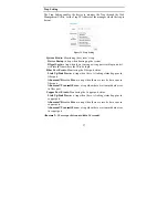
Page 38: ...on the Status button to display the device status on this screen It will display the System Status Port Status VLAN Status Trunk Status and Mirror Status Press Refresh when you need to renew the poste...

Page 39: ...34 Statistics The Statistics Menu screen will show the status of each port packet count Figure 36 For detailed packet information click on the ID parameter as in Figure 37...

Page 40: ...35 Figure 37 Port Statistic...

Page 41: ...you can easily recognize the device by using the System Name and the Location Name The Login Timeout is to set the idle time out for security issues When there is no action in running the Web Smart Ut...

Page 42: ...vents Monitoring the Fiber port status Link Up Link Down a trap when there is linking status happens in fiber port Abnormal Receive Error a trap when there are receive data error in fiber port Abnorma...

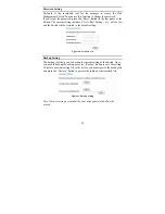
Page 43: ...and the Switch will be restored to the default setting Figure 40 Set Password Backup Setting The backup tools help you to backup the current setting of the Switch Once you need to backup the setting...

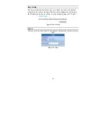
Page 44: ...ing from the factory Be aware that the entire configuration will be reset the IP address of the device will be set to the default setting of 192 168 0 1 Figure 42 Reset Setting Logout When you select...

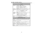
Page 45: ...x Topology Star Network Cables 10BASET 2 pair UTP Cat 3 4 5 up to 100m 100BASE TX 2 pair UTP Cat 5 up to 100m 1000BASE T 4 pair UTP Cat 5 up to 100m Fiber module mini GBIC Fiber module Number of Ports...

Page 46: ...Table 8K entries per device Packet Filtering Forwarding Rate 10Mbps Ethernet 14 880 pps 100Mbps Fast Ethernet 148 800 pps 1000Mbps Gigabit Ethernet 1 488 000 pps MAC Address Learning Automatic update...

Page 47: ...ng sold As Is without any warranty whatsoever including without limitation the Limited Warranty as described herein notwithstanding anything stated herein to the contrary Submitting A Claim The custom...

Page 48: ...pyright Statement No part of this publication or documentation accompanying this product may be reproduced in any form or by any means or used to make any derivative such as translation transformation...

Page 49: ...egistration Register online your D Link product at http support dlink com register Product registration is entirely voluntary and failure to complete or return this form will not diminish your warrant...

Page 50: ...nek Aurum ul Walic w 11 PL 00 851 Warszawa Poland TEL 48 0 22 583 92 75 FAX 48 0 22 583 92 76 URL www dlink pl Hungary R k czi t 70 72 HU 1074 Budapest Hungary TEL 36 0 1 461 30 00 FAX 36 0 1 461 30 0...

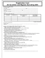
Page 51: ...site 1 employee 2 9 10 49 50 99 100 499 500 999 1000 or more 3 What network protocol s does your organization use XNS IPX TCP IP DECnet Others_____________________________ 4 What network operating sys...

Page 52: ......
Reviews: