background image

D-Link Switch User Manual


10 

Appendix B - Regulatory Statements


FCC Warning 

This equipment has been tested and found to comply with the regulations for a Class A digital device, pursuant 

to Part 15 of the FCC Rules. These limits are designed to provide reasonable protection against harmful 

interference when the equipment is operated in a commercial environment. This equipment generates, uses, 

and can radiate radio frequency energy and, if not installed and used in accordance with this user’s guide, may 

cause harmful interference to radio communications. Operation of this equipment in a residential area is likely 

to cause harmful interference, in which case the user will be required to correct the interference at his/her own 

expense. 

 
CE Mark Warning 

This is a Class A product. In a domestic environment, this product may cause radio interference, in which case 

the user may be required to take adequate measures. 

 
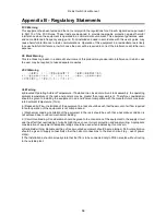
VCCI Warning 


UL Warning 

a) Elevated Operating Ambient Temperature- If installed in a closed or multi-unit rack assembly, the operating 

ambient temperature of the rack environment may be greater than room ambient.  Therefore, consideration 

should be given to installing the equipment in an environment compatible with the manufacturer's maximum 

rated ambient temperature (Tmra). 
 b) Reduced Air Flow- Installation of the equipment in a rack should be such that the amount of air flow required 

for safe operation of the equipment is not compromised. 
 c) Mechanical Loading- 

capitalize

 of the equipment in the rack should be such that a hazardous condition is 

not achieved due to uneven mechanical loading. 
 d) Circuit Overloading- Consideration should be given to the connection of the equipment to the supply circuit 

and the effect that overloading of circuits might have on over current protection and supply wiring.  Appropriate 

consideration of equipment nameplate ratings should be used when addressing this concern. 
e) Reliable Earthing- Reliable earthing of rack-mounted equipment should be maintained.  Particular attention 

should be given to supply connections other than direct connections to the branch circuit (e.g., use of power 

strips). 
f) The Installation instructions clearly state that the ITE is to be connected only to POE networks without routing 

to the outside plant. 

Summary of Contents for DGS-1026MP

Page 1: ......

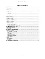
Page 2: ... the Switch in a Rack 5 Powering on the Switch 6 Connecting the Switch 6 Connect to an End Node 6 Connect to a Hub or Switch 7 Connect to a Network Backbone or Server 7 Understanding the Switch s Features 8 Power Over Ethernet PoE 8 Power Saving 8 Appendix A Technical Specifications 9 Hardware Specifications 9 Key Components Performance 9 Ports 9 Port Standards 9 Physical Environment 9 Emission EM...

Page 3: ...tion to use the device properly A CAUTION indicates potential property damage or personal injury Copyright and Trademarks Information in this document is subjected to change without notice 2016 D Link Corporation All rights reserved Reproduction in any manner whatsoever without the written permission of D Link Corporation is strictly forbidden Trademarks used in this text D Link and the D LINK log...

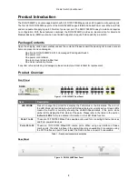
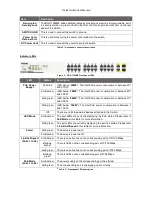
Page 4: ... Guide If any item is found missing or damaged please contact your local retailer for replacement Product Overview Front Panel Figure 1 DGS 1026MP Front Panel Item Description LED MODE Press to change the port LEDs to display the PoE status or the link status The color of the LED Mode light will indicate which LED status display is currently active Green LEDs means the Switch is currently showing ...

Page 5: ...on is between 101 and 200 W Solid green LED below 100W The total PoE power consumption is between 1 and 100 W Off There are no PoE powered devices attached to the Switch LED Mode Solid amber The port LEDs are currently displaying the PoE status Please refer to PoE Mode in this table for more information Solid green The port LEDs are currently displaying the port link status Please refer to Link Ac...

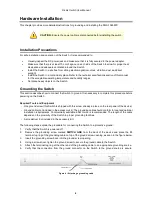
Page 6: ...re powering on the Switch Required Tools and Equipment One ground screw this Switch is shipped with this screw already in place on the rear panel of the device Ground cable not included in the accessory kit The grounding cable should conform to local and national installation requirements Commercially available 6 AWG wire is recommended The length of the cable depends on the proximity of the Switc...

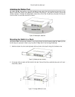
Page 7: ...ottom panel of the Switch Figure 5 Attaching the rubber feet Mounting the Switch in a Rack The DGS 1026MP can be easily mounted in a rack using the two provided mounting brackets Make sure that the front panel is exposed in order to view the LEDs Please refer to the following illustrations 1 Attach and fasten the rack mounting brackets to each side of the Switch using the included screws Figure 6 ...

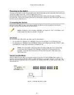
Page 8: ...es use Category 5 or 5e UTP STP cable For connections to 100BASE TX and 1000BASE T devices use Category 5e or better UTP STP cable All 1000BASE T connections will operate in full duplex mode Connect to an End Node Use a standard Ethernet cable to connect the Switch to PCs with a 10 100 1000 Mbps RJ45 interface or connect and power remote IEEE 802 3af at compliant PoE devices such as IP cameras or ...

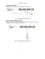
Page 9: ...tch or hub Figure 9 Connecting the Switch to another switch or hub Connect to a Network Backbone or Server Use any port on the device to connect the Switch to a network backbone or network server When linking to a 1000BASE T device the port operates in full duplex mode Figure 10 Connecting the Switch to another switch or hub ...

Page 10: ...d If the device is another PoE powered device the Switch will disconnect the power on the port with the higher port number in order to power the new device PoE Port Priority The DGS 1026MP is configured to have predefined PoE priorities for all PoE ports to prevent problems such as power budget overloading Lower number ports have a higher priority for supplying power than higher number ports i e p...

Page 11: ... 802 3af at ports 1 to 24 Physical Environment Dimensions 440 x 250 4 x 44 mm Weight 3 1 kg Internal Power Supply AC input 100 240 VAC 50 60Hz Acoustic 41 8 dB A at low speed 55 1 dB A at high speed Operation Temperature 0 to 50 C Storage Temperature 40 to 70 C Operation Humidity 0 to 95 RH Storage Humidity 0 to 95 RH Emission EMI Certifications FCC class A CE Class A VCCI Class A C Tick CCC BSMI ...

Page 12: ...operating ambient temperature of the rack environment may be greater than room ambient Therefore consideration should be given to installing the equipment in an environment compatible with the manufacturer s maximum rated ambient temperature Tmra b Reduced Air Flow Installation of the equipment in a rack should be such that the amount of air flow required for safe operation of the equipment is not...

Page 13: ......

Reviews: