11
Step 2: Eject the DFE-680TX from the Computer
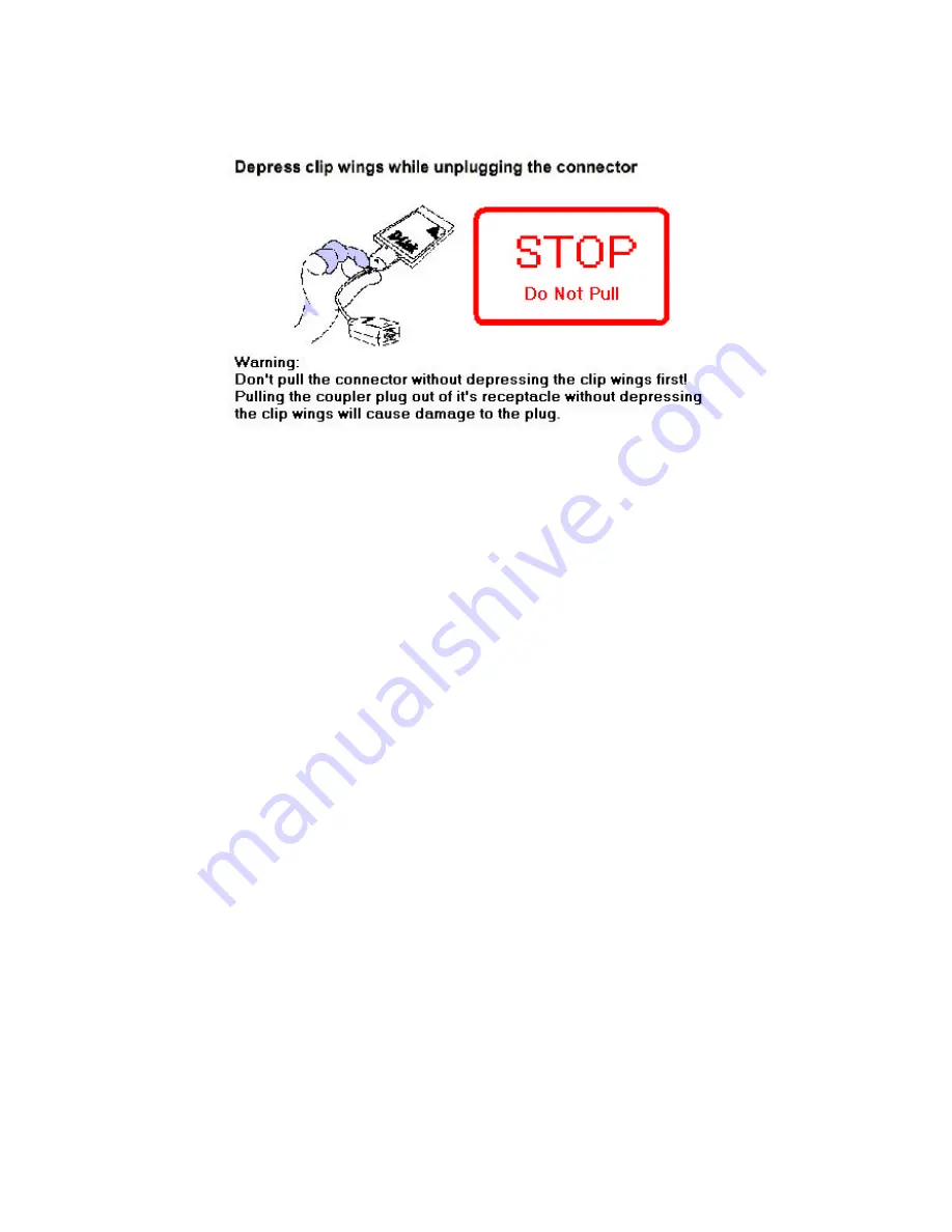
Firmly press the computer's PC Card Eject button to disengage the DFE-680TX from the
slot connector. The DFE-680TX will then protrude from the PC Card slot. Grip its
protruding end between your fingers and withdraw it from the PC Card slot.
Connect the Network Cable
Category 5 UTP cable is good enough to qualify under both the Fast Ethernet cabling
rules and the traditional Ethernet cabling rules. The maximum individual cable run
between any station and its supporting hub or switch is 100m. The maximum individual
cable run joining two hubs is 10m in general, but is 100m when both hubs qualify as
Ethernet Class 2 Repeaters (
all
D- Link Ethernet hubs do qualify). But these cable runs
may need to be shorter than the given individual maximum lengths, because their lengths
are also restricted by the rule that the maximum
aggregated
cable run between any two
stations is 205m.
Connecting for Fast Ethernet
Category 5 UTP cable is required for Fast Ethernet operation. The maximum length of
cable between the DFE-680TX and the supporting hub is 300 ft. The cable must be
“ straight” (not a“crossover” cable), with an RJ-45 plug at each end. Make the network
connection by plugging one end of the cable into the RJ-45 receptacle of the media
coupler, and the other end into a port of the supporting hub.
Summary of Contents for DFE-680TX
Page 16: ...14 Figure2 Select Next to continue installation ...
Page 17: ...15 Figure3 Ensure that the Specify location box is checked and click Next ...
Page 18: ...16 Figure4 Click Next to continue ...
Page 19: ...17 Figure5 The Digital Signature Not Found window appears Click Yes to continue ...
Page 20: ...18 Figure6 Click Finish to complete the DFE 680TX Ethernet Card installation ...
Page 22: ...20 Figure8 Select Hardware and then click the Device Manager button ...
Page 27: ...25 Figure4 Click Finishto complete driver installation ...
Page 29: ...27 Windows 98 Driver install Figure1 Select Next ...
Page 30: ...28 Figure2 Select Next ...
Page 31: ...29 Figure3 Enter CD ROM drive or click on the Browse button and select CD ROM drive ...
Page 32: ...30 Figure4 Driver file name select Next Figure5 Insert 98 CD ROM then click on OK button ...
Page 34: ...32 Figure7 Finish ...
Page 43: ...ii VCCI Warning ...


