background image

28

Connector Pinouts

 Table B-1:  RJ-45 Connector Pinouts

RJ-45 Connector Pinouts

Pin

MDI Signal

1

TD+ (Transmit)

2

TD- (Transmit)

3

RD+ (Receive)

4

NC

5

NC

6

RD- (Receive)

7

NC

8

NC

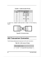
A sketch for crossover cable pinouts is shown in the following
figure.


Figure B-2  Crossover Cable

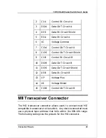
AUI Transceiver Connector

The following table gives the pinouts for the AUI connector.

 Table B-2:  AUI Connector Pinouts

Pin Circuit

Use

1

CI-S

Control IN Circuit Shield

Summary of Contents for DES-815

Page 1: ...DES 815 10 100 Fast Ethernet Switch User s Guide Rev 02 Aug 1997 6DES815 02 Printed In Taiwan RECYCLABLE ...

Page 2: ...h am Geräten befinden sind zu beachten 12 Wird das Gerät über einen längeren Zeitraum nicht benutzt sollten Sie es vom Stromnetz trennen Somit wird im Falle einer Überspannung eine Beschädigung vermieden 13 Durch die Lüftungsöffnungen dürfen niemals Gegenstände oder Flüssigkeiten in das Gerät gelangen Dies könnte einen Brand bzw Elektrischen Schlag auslösen 14 Öffnen Sie niemals das Gerät Das Gerä...

Page 3: ...IN THE PRODUCT DOES NOT EXIST OR WAS CAUSED BY THE CUSTOMER S OR ANY THIRD PERSON S MISUSE NEGLECT IMPROPER INSTALLATION OR TESTING UNAUTHORIZED ATTEMPTS TO REPAIR OR ANY OTHER CAUSE BEYOND THE RANGE OF THE INTENDED USE OR BY ACCIDENT FIRE LIGHTNING OR OTHER HAZARD LIMITATION OF LIABILITY IN NO EVENT WILL D LINK BE LIABLE FOR ANY DAMAGES INCLUDING LOSS OF DATA LOSS OF PROFITS COST OF COVER OR OTHE...

Page 4: ...ny warranty All products with lifetime warranty have a standard five year warranty To qualify for lifetime warranty the enclosed Product Registration Card must be completed and returned to D Link within ninety 90 days of purchase Warranty service may be obtained by contacting a D Link office within the applicable warranty period for a Return Material Authorization RMA number If a Registration Card...

Page 5: ...erica D Link Systems Inc 5 Musick Irvine CA 92618 Tel 1 714 455 1688 Fax 1 714 455 2521 In Europe and Israel D Link Europe D Link House 6 Garland Road Stanmore London HA7 1DP U K Tel 44 181 235 5555 Fax 44 181 235 5500 In the Middle East except Israel Asia Oceania and Africa D Link Corporation No 233 2 2nd F Pao Chiao Road Hsin Tien Taipei Taiwan Tel 886 2 916 1600 Fax 886 2 914 6299 ...

Page 6: ...comply with the limits for a Class A digital device pursuant to Part 15 of the FCC Rules These limits are designed to provide reasonable protection against harmful interference when the equipment is operated in a commercial environment This equipment generates uses and can radiate radio frequency energy and if not installed and used in accordance with this user s guide may cause harmful interferen...

Page 7: ...ntroduction 1 100Mbps Fast Ethernet Introduction 2 100BASE TX Technology Overview 3 Cables and Connectors 3 Topology 3 Network 4 Hubs 4 Connectivity Rules 5 Switching Technology 5 Benefits of Switching 6 10 100 Switching Technology 6 Product Features 7 Packing List 8 Front Panel 8 Ports 8 LED Indicators 11 Rear Panel 13 Duplex Mode Switch 14 ...

Page 8: ...ower 18 Network Connections 18 10 100Mbps Ports 18 10Mbps Ports 19 Cable Types 19 Setting the Duplex Mode 20 Network Configuration Examples 21 Fast Ethernet Server Connection 22 LAN Microsegmentation 23 A SPECIFICATIONS 25 B CONNECTOR PINOUTS 27 RJ 45 Connectors 27 AUI Transceiver Connector 28 MII Transceiver Connector 29 1 ...

Page 9: ...t network capabilities in a highly flexible rack mountable package Purpose This manual discusses how to install and use the 10 100 Fast Ethernet Switch Audience This manual is intended for network administrators with Background in LAN bridge concepts Understanding of IEEE 802 3 Ethernet and 100BASE TX Fast Ethernet networking concepts Understanding of how to install local area networks LANs ...

Page 10: ... 100 Fast Ethernet Switch Chapter 2 includes information on table and rack mounted installation connecting power network connections setting the communications mode and cascade and provides some network configuration examples Appendix A Specifications Lists the technical specifications of the product Appendix B Connector Pinouts Describes the connector pinouts of the 10 100 Fast Ethernet Switch po...

Page 11: ... Fast Ethernet with 10Mbps Ethernet networks seamlessly The speed migration design will bridge high bandwidth Fast Ethernet network segments to traditional 10Mbps Ethernet network segments quickly and simply The DES 815 complies with IEEE802 3u 100BASE TX IEEE802 3 and 10BASE T standards It has 12 10Mbps twisted pair ports two 10 100Mbps twisted pair ports and one MII port The DES 815 provides bot...

Page 12: ...traffic Recognizing this need for greater bandwidth and lower latency a variety of technologies such as FDDI ATM and 100Mbps Fast Ethernet have been adopted by many vendors 100Mbps Fast Ethernet technology stands out as the most inexpensive and smoothest migration path for existing 10Mbps Ethernet users 100Mbps Fast Ethernet is a relatively new standard specified by the IEEE 802 3 LAN committee It...

Page 13: ...o known as a segment or collision domain and these workgroups can be easily interconnected through switches bridges or routers to form one LAN large enough to encompass a high rise building or campus environment Recent innovations in LAN hub technology such as stackable hubs coupled with the decreasing cost of switches bridges and routers allow the design of low cost efficient Fast Ethernet workgr...

Page 14: ...the other ports by first translating them to digital signals and then retranslating them back to line signals These translations are necessary when connecting various network media to the same collision domain such as when combining two wire pair 100BASE TX media with four wire pair 100BASE T4 media Only one Class I hub can exist within the same collision domain thus this type of hub cannot be cas...

Page 15: ...tween Ethernet and Fast Ethernet LAN segments at the MAC address level of the Ethernet protocol The difference between switched Ethernet 10Mbps 100Mbps or both and traditional Ethernet is analogous to the difference between a private phone line and a party line With switched Ethernet each workgroup has a private line so that transmitted packets don t have to wait as long to gain access to the netw...

Page 16: ... sufficiently sophisticated platform for users to be able to take full advantage of such client server applications Fast Ethernet switching not only satisfies both technical and business needs it also preserves the current investment in the huge 10BASE T Ethernet installed base Compatibility with 10Mbps Ethernet ensures that users will be able to migrate to Fast Ethernet at a pace appropriate to t...

Page 17: ...ex and half duplex capability on all ports with each user configurable through the Duplex Mode Switch on the rear panel Flexibility of application from segmentation of a large LAN to client server maximization to dedicated connections for high priority single users Support for IEEE 802 3 10BASE 2 10BASE T IEEE 802 3u and 100BASE TX standards Εxtensive LED indicators to facilitate troubleshooting a...

Page 18: ...ernet Switch This User s Guide An AC Power Cord Two Rack Mount Brackets and screws Four adhesive backed rubber feet Front Panel The 10 100 Fast Ethernet Switch front panel includes network connectors and LED indicators for ease of use Figure 1 10 100 Fast Ethernet Switch Front Panel Ports The product comes with twisted pair ports These ports can be used to connect to individual stations in need of...

Page 19: ...sting LAN to improve bandwidth utilization Connect single users either to provide power users with greater access and thus speed or multiple users for high bandwidth access to a shared network server Uplink connections for lower tier switches 10 100Mbps Ports The 10 100Mbps twisted pair ports are standard RJ 45 connectors for use with unshielded or shielded twisted pair UTP STP wiring These ports ...

Page 20: ...Mbps 100m Category 3 4 or 5 UTP STP 10 100Mbps RJ 45 10 20Mbps 100 200 Mbps 100m Category 5 UTP STP Uplink Port The uplink port is used for higher tier connections to more advanced switches or other network devices Please note that if you are using the uplink port you will be unable to use port one as these two ports are logically linked Note A crossover cable must be used when connecting from the...

Page 21: ...ver Connector The MII transceiver connector is a 10 100Mbps port for connecting a fiber optic or additional Fast Ethernet segment via a transceiver The MII connector like ports 1 and 2 can auto detect the speed of a device connected and auto adjust to operate at either 10Mbps or 100Mbps Pinouts for this connector are listed in Appendix B LED Indicators The 10 100 Fast Ethernet Switch has extensive...

Page 22: ...pective port is properly connected to a powered on device and blinks green when packets are being transmitted or received FDX Collision Col LED This indicator is green when the respective port is operating in full duplex mode Otherwise it is off for half duplex operation This indicator blinks yellow when there are collisions occurring on the respective port System Load LED Meter This LED meter ind...

Page 23: ...e above They are only lit and active when an MII transceiver is connected to the switch 100M LEDs These indicators are green when port 1 port 2 or the MII connector are connected to a device operating at 100Mbps If any of these LEDs are off then the port it corresponds to is either not connected or is connected to a device operating at 10Mbps Rear Panel The rear panel of the 10 100 Fast Ethernet S...

Page 24: ...ch for ports 1 2 and the MII connector down is auto detect up is full duplex For ports 1 and 2 the 10 100Mbps variable speed ports Auto means that the appropriate duplex mode is set by the hub according to the capabilities of the device connected and FDX manually sets the ports to full duplex mode Regardless of the duplex mode setting the speed setting of ports 1 and 2 is automatically detected Fo...

Page 25: ... option to install the product on a table or mount it in a standard network rack When installing choose a sturdy level surface in a ventilated area that is dust free and away from heat vents warm air exhaust from other devices and direct sunlight Avoid proximity to large electric motors or other electromagnetic equipment Observe the following guidelines when choosing a location for the 10 100 Fast...

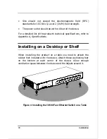
Page 26: ...uct s technical specifications refer to Appendix A Specifications Installing on a Desktop or Shelf When installing the product on a table you need to attach the rubber feet included with the device Attach these cushioning feet on the bottom at each corner of the device Allow enough ventilation space between the device and the objects around it Figure 4 Installing the 10 100 Fast Ethernet Switch on...

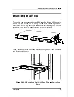
Page 27: ...nch rack which can be placed in a wiring closet with other equipment Attach the mounting brackets on the switch s front panel one on each side and secure them with the screws provided Then use the screws provided with the equipment rack to mount the switch in the rack Figure 5A 5B Installing the 10 100 Fast Ethernet Switch in a Rack ...

Page 28: ...00 Fast Ethernet Switch is set for full duplex operation the device or LAN connected to that port should also be set for full duplex operation The following sections discuss the requirements for each operating mode 10 100Mbps Ports Port 1 and port 2 are variable speed ports and require Category 5 unshielded twisted pair or shielded twisted pair UTP STP cable to run at 100Mbps The attached station ...

Page 29: ...verters include fiber optic capabilities and can use fiber optic cables up to 2 km long 10Mbps Ports These ports require Category 3 4 or 5 unshielded twisted pair or shielded twisted pair UTP STP cable They can be used to connect to individual workstations servers or other 10BASE T devices The attached station must be within 100 meters of the 10 100 Fast Ethernet Switch When connecting a workstati...

Page 30: ... Through Uplink Crossover X Setting the Duplex Mode Each port of the device can be set for half duplex or full duplex operation The two 10 100Mbps ports and the MII connector can be set to either full duplex or auto detect duplex mode At half duplex operation packet transmission and reception do not occur simultaneously thus communication speed is limited to 100Mbps using 100BASE TX mode and 10Mbp...

Page 31: ...ice To set a port to full duplex operation slide the corresponding duplex switch up To set for half duplex set the duplex switch down To set port 1 port 2 or the MII connector to auto duplex mode detect set the corresponding switch down Figure 7 Setting the Duplex Mode Network Configuration Examples This section provides sample configurations showing ways you might use the 10 100 Fast Ethernet Swi...

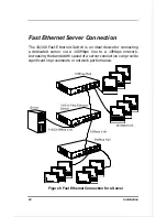
Page 32: ...thernet Switch is an ideal device for connecting a dedicated server via a 100Mbps line to a 10Mbps network Increasing the bandwidth speed of a server connection can provide significant improvements in network performance Figure 8 Fast Ethernet Connection for a Server ...

Page 33: ...rpose for the 10 100 Fast Ethernet Switch is to microsegment an existing LAN to improve network latency rates and increase overall performance The 100Mbps ports on the switch can be used to connect those segments which require greater throughput Figure 9 Microsegmenting a LAN and Adding 100Mbps Segments ...

Page 34: ......

Page 35: ...IEEE 802 3 100BASE TX IEEE 802 3u 100Mbps 100BASE TX RJ 45 Full or Half Duplex 100 200Mbps 10Mbps 10BASE T RJ 45 Full or Half Duplex 10 20Mbps Performance Filtering Rate 10Mbps Port 14880 pps 100Mbps Port 148800 pps Forwarding Rate 10Mbps Port 14880 pps 100Mbps Port 148800 pps LED Indicators Power AUI MII Link Act FDX Col 100M System Load Meter Dimensions 441 x 207 x 45 mm W x D x H ...

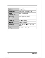
Page 36: ... 6 5 lbs Power Input 100 240 VAC 50 60Hz 1A Power Consumption 40 Watt maximum Operating Temperature 32 122 F 0 50 C Humidity 5 90 Storage Altitude 10 000 ft 3048 m Emissions FCC part 15 Class A VCCI 1 CE Mark Safety UL CSA and TUV GS ...

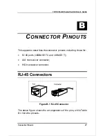
Page 37: ...S This appendix describes the connector pinouts including those for RJ 45 ports 100BASE TX and 10BASE T AUI transceiver connector MII transceiver connector RJ 45 Connectors Figure B 1 RJ 45 Connector The above figure shows the arrangements of the pins while Table B 1 lists the pinouts ...

Page 38: ...ansmit 3 RD Receive 4 NC 5 NC 6 RD Receive 7 NC 8 NC A sketch for crossover cable pinouts is shown in the following figure Figure B 2 Crossover Cable AUI Transceiver Connector The following table gives the pinouts for the AUI connector Table B 2 AUI Connector Pinouts Pin Circuit Use 1 CI S Control IN Circuit Shield ...

Page 39: ...CI B Control IN Circuit B 10 DO B Data OUT Circuit B 11 DO S Data OUT Circuit Shield 12 DI B Data IN Circuit B 13 VP Voltage Plus 14 VS Voltage Shield 15 CO B Control OUT Circuit B MII Transceiver Connector The MII transceiver connector allows users to connect most MII compatible transceivers to the switch Any device connected must use a physical layer address that falls within the 00h 10h range T...

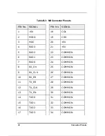
Page 40: ...5V 18 COL 2 MDIO 19 CRS 3 MDC 20 5V 4 RXD3 21 5V 5 RXD2 22 COMMON 6 RXD1 23 COMMON 7 RXD0 24 COMMON 8 RX_DV 25 COMMON 9 RX_CLK 26 COMMON 10 RX_ER 27 COMMON 11 TX_ER 28 COMMON 12 TX_CLK 29 COMMON 13 TX_EN 30 COMMON 14 TXD0 31 COMMON 15 TXD1 32 COMMON 16 TXD2 33 COMMON 17 TXD3 34 COMMON ...

Page 41: ...10 100 Fast Ethernet Switch User s Guide 31 35 COMMON 38 COMMON 36 COMMON 39 COMMON 37 COMMON 40 5V 6 ...

Page 42: ......

Page 43: ...ENMARK Naverland 2 DK 2600 Glostrup Copenhagen Denmark TEL 45 43 969040 FAX 45 43 424347 SINGAPORE D LINK SINGAPORE PTE LTD 77 Science Park Drive 03 03 CINTECH III Singapore Science Park Singapore 118256 EL 65 7746233 FAX 65 7746322 AUSTRALIA D LINK AUSTRALIA PTY LTD Unit 16 390 Eastern Valley Way Roseville NSW 2069 Australia TEL 61 2 94177100 FAX 61 2 94171077 CHINA D LINK BEIJING 15th Floor Scie...

Page 44: ...will the product primarily be used oHome oOffice oTravel oCompany Business oHome Business oPersonal Use 2 How many employees work at installation site o1 employee o2 9 o10 49 o50 99 o100 499 o500 999 o1000 or more 3 What network protocol s does your organization use oXNS IPX oTCP IP oDECnet oOthers_____________________________ 4 What network operating system s does your organization use oD Link LA...

Page 45: ......

Page 46: ......

Reviews: