background image

58

D-Link DCS-6513 User Manual

Section 3: Configuration

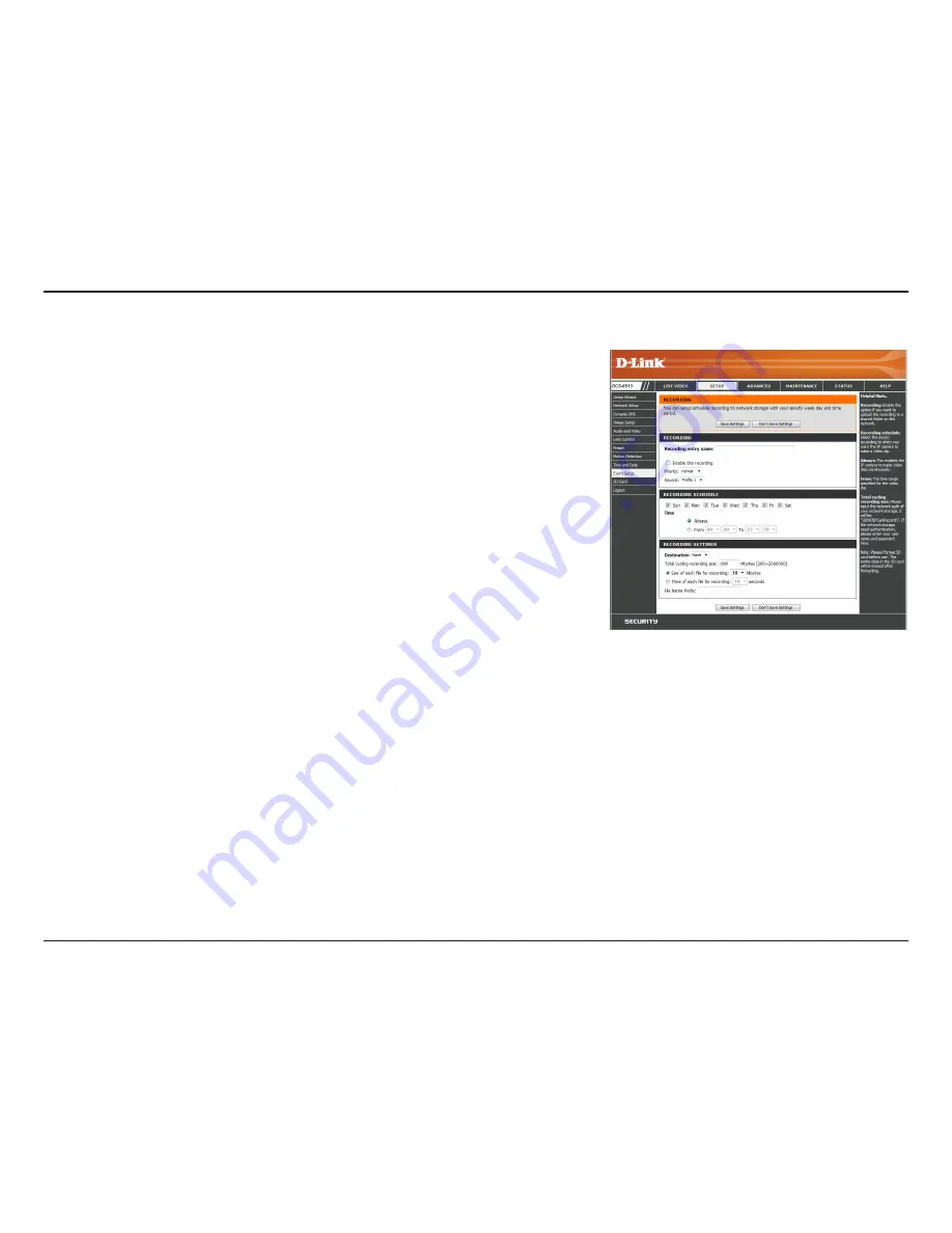
Add Recording

Recording entry name:

Enable this recording:

Priority:

Source:

Recording schedule:

Recording settings:

Destination:

Total cycling recording size:

The unique name of the entry.

Select this to enable the recording function.

Set the priority for this entry. The entry with a higher 

priority value will be executed first.

The source of the stream.

Scheduling the recording entry.

Configuring the setting for the recording.

Select the folder where the recording file will be stored.

Please input a HDD volume between 1MB and 2TB for 

recording space. The recording data will replace the 

oldest record when the total recording size exceeds this 

value. For example, if each recording file is 6MB, and the 

total cyclical recording size is 600MB, then the camera 

will record 100 files in the specified location (folder) and 

then will delete the oldest file and create new file for 

cyclical recording.

Please note that if the free HDD space is not enough, the 

recording will stop. Before you set up this option please 

make sure your HDD has enough space. It is advised not 

to save other files in the same folder as recording files. 

Here you can configure and schedule the recording settings. After making any changes, 

click the 

Save Settings


button to save your changes.

Summary of Contents for DCS 6513

Page 1: ...User Manual Version 1 0 February 25 2013 DCS 6513 Full HD WDR Day Night Outdoor Dome Network Camera ...

Page 2: ...iption 1 0 February 25 2013 DCS 6513 Revision A1 with firmware version 1 00 Trademarks D Link and the D Link logo are trademarks or registered trademarks of D Link Corporation or its subsidiaries in the United States or other countries All other company or product names mentioned herein are trademarks or registered trademarks of their respective companies Copyright 2013 D Link Corporation All righ...

Page 3: ...xis Gimbal 24 Software Installation 25 D ViewCam Setup Wizard 28 Configuration 30 Using the Configuration Interface 30 Live Video 31 Setup 33 Setup Wizard 33 Network Setup 39 Dynamic DNS 42 Image Setup 43 Audio and Video 45 Lens Control 47 Preset 48 Motion Detection 50 Time and Date 51 Event Setup 52 SD Card 60 Advanced 61 Digital Input Output 61 ICR and IR 62 HTTPS 63 Access List 64 Maintenance 6...

Page 4: ... Note Usingapowersupplywithadifferentvoltagethantheoneincludedwithyourproductwillcausedamageandvoidthewarrantyforthisproduct DCS 6513 Full HD WDR Day Night Outdoor Dome Network Camera Power adapter CD ROM with User Manual and software Weather Shield 37mm Screws for Weather Shield Quick Install Guide Extension Adapter Security Wrench Cable Cover Rubber Plug ...

Page 5: ...IP67certifiedweatherproofhousingdesignedforbothindoorandoutdoorapplications Thebuilt inremovable IR cut filter and IR LEDs gives the DCS 6513 the capability to view up to 60 feet at night The DCS 6513 also incorporates Power over Ethernet PoE allowing it to be easily installed in a variety of locations without the need for supplemental power cabling The combination of IP67 housing IR Cut Filter IR...

Page 6: ...3monitorsandautomaticallyregulatesitstemperaturetoensureoptimalperformanceeveninextremeconditions Itbalancesfanuseagainst a built in heater based on a range of preset thermostatic settings This gives the DCS 6513 the ability to perform in the most demanding of environments Remote Monitoring Utility The D ViewCam application adds enhanced features and functionality for the Network Camera and allows...

Page 7: ...ons and switches between color and infrared accordingly 3 IR LEDs Infrared LEDs illuminate the camera s field of view at night 4 Power Status LED Indicates the camera s current status 5 Protective Casing The camera is housed in an IP67 certified weatherproof casing which protects it against rain and dust This case is also IK10 certified vandal resistant 2 3 5 4 1 Front Hardware Overview ...

Page 8: ...installation 2 Power Connector Power connector for the provided 12V DC power adapter 3 Audio In A In Connects to a microphone 4 Audio Out A Out Connects to a speaker 5 DI DO Connector I O connectors for external devices 12V DC output 6 Reset Button Press and hold the recessed button for ten seconds to reset the camera 7 24V Power Connector Connects to 24V AC power supply 2 1 6 7 4 3 5 ...

Page 9: ... recorded images and video 1 Disassemble the Camera Open the camera enclosure by loosening the four screws Then lift the dome off the base of the camera Install the SD Card Push the SD card into the camera with the gold contacts oriented towards the base of the camera To eject the SD card push the SD card into the slot ...

Page 10: ... Attach the cables to the corresponding cable connectors Figure 2 1 3 Locate a suitable position on the ceiling for the mounting plate to be installed 4 Use the mounting template to mark the holes for installation 5 Cut an access hole in the ceiling for the cables 6 Drill four separate 6mm holes corresponding to the holes in the mounting template and insert the plastic anchors into these holes 7 A...

Page 11: ...Connect the Ethernet cable and the power cable threading them through the hole in the ceiling Figure 2 2 2 Push the dome body up over the base of the camera 3 Attach the dome to the base of the camera using the three long screws and the provided security screw Figure 2 2 ...

Page 12: ...on 2 Assembly and Installation Exposed Cable Installation Style 2 Exposed Cable Installation 1 Disassemble the camera enclosure see page 9 2 Remove the small screw to release the faceplate on the side of the base of the camera Figure 2 3 ...

Page 13: ...emove the small screw to release the faceplate on the side of the base of the camera 3 Thread the cables through the waterproof plugs on the side of the base of the camera Attach the cables to the corresponding cable connectors see page 10 4 Attach the dual holed plate to the base of the camera Figure 2 4 Figure 2 4 ...

Page 14: ...3 Use the mounting template to mark the holes for installation 4 Drill four separate 6mm holes corresponding to the holes in the mounting template and insert the plastic anchors into these holes 5 Attach the surface bracket to the ceiling using the screws provided 6 Place the dome body onto the base of the camera Figure 2 6 7 Attach the dome to the base of the camera using the three long screws an...

Page 15: ... template 4 Drill four separate 6mm holes corresponding to the holes in the mounting template and insert the plastic anchors into these holes 5 Place the rubber seal between the pendant bracket and the ceiling to ensure a waterproof seal between the ceiling and the bracket Figure 3 2 6 Attach the pendant bracket to the ceiling using the screws provided 7 Attach the bracket cap to the bottom of the...

Page 16: ...513 User Manual Section 2 Assembly and Installation 1 Connect the Ethernet cable and the power cable then thread them through the pendant bracket 2 Place the dome body onto the base of the camera Figure 3 3 Figure 3 3 ...

Page 17: ...17 D Link DCS 6513 User Manual Section 2 Assembly and Installation 1 Attach the dome to the base of the camera using the three long screws and the provided security screw ...

Page 18: ...o the holes in the mounting template and insert the plastic anchors into these holes 5 Place the rubber seal between the wall mount bracket and the wall to ensure a waterproof seal between the wall and the bracket Figure 4 2 6 Attach the wall mount bracket to the wall using the screws provided 7 Attach the bracket cap to the bottom of the wall mount bracket by rotating the cap counterclockwise to ...

Page 19: ... 2 Assembly and Installation Dome Camera 10 Place the dome body onto the base of the camera Figure 4 3 11 Attach the dome to the base of the camera using the three long screws and the provided security screw Figure 4 3 Figure 4 4 Wall Mount ...

Page 20: ...unting or connecting the camera in its final location To install the weather shield you will require the 37mm screws which were included in the product package Step 1 Using a screwdriver remove the existing two screws which were pre installed in the collar of the camera Step 2 Place the weather shield over the dome of the camera and align the screw holes with the holes in the collar of the camera ...

Page 21: ...User Manual Section 2 Assembly and Installation Connection Using 12V DC Power Adapter 1 Connect the network camera to a switch via an Ethernet cable 2 Connect the supplied power cable from the camera to a power outlet 1 2 ...

Page 22: ...ser Manual Section 2 Assembly and Installation Connection Using 24V AC Power Wiring 1 Connect the network camera to a switch using an Ethernet cable 2 Connect the supplied power cable from the camera to a power source 1 2 ...

Page 23: ...l Section 2 Assembly and Installation Connection with a PoE Switch 1 If you are using a PoE switch connect the IP camera to the switch via an Ethernet cable which will provide transmission of both power and data over a single cable ...

Page 24: ...eved Tighten the pan screw once completed Loosen the tilt screws on both sides of the camera and turn the lens module up and down until the desired position is achieved Tighten the tilt screws once completed Turn the lens to adjust the IP camera s image until the desired orientation is achieved and then tighten the image adjustment screw once completed Adjusting the lens 3 axis Gimbal ...

Page 25: ...oWindows click Start Run In the Run command box type D DCS6513 exe where D represents your CD ROM drive Step 2 Click Setup Wizard to begin Step 3 Accept the EndUserLicenceAgreement and follow the on screen prompts to install the camera Step 4 Select your camera from the list and then click Wizard If you have multiple cameras you can identify them by the MAC ID printed on the label on the back of y...

Page 26: ... create and confirm a password for your device Click Next to continue Step 6 Select Static IP if you want to manually enter the network settings of your camera or DHCP if you want your router or DHCP server to automatically assign the camera its network settings Click Next to continue Note Select DHCP if you are unsure of which settings to choose Click Next to continue ...

Page 27: ...ra s settings and click Restart The LED on the front of the DCS 6513 will blink and then turn solid green once it successfully connects to your network Step 8 YourDCS 6513cameraisnowsetup ClickExittoexitthewizard Youcanskipto Configuration on page 30 for advanced configuration of your camera ...

Page 28: ...ly You may use the software to configure all the advanced settings for your cameras D ViewCam is a comprehensive management tool for IP surveillance Step 1 Insert the CD ROM into the CD drive Click Install D ViewCam Software from menu and select D ViewCam to install the VMS software Step 2 Follow the Installation Wizard to install D ViewCam D ViewCam Setup Wizard ...

Page 29: ...y and Installation Step 3 Click Finish to complete the installation Step 4 To start D ViewCam select Start All Programs D Link D ViewCam Main Console Step 5 For more detailed operation of using D ViewCam software please refer to the D ViewCam manual ...

Page 30: ...6513 At the end of theWizard click Link or enter the IP address of your camera into a web browser such as Firefox To log in use the User name admin and the password you created in the InstallationWizard If you did not create a password the default password is blank After entering your password click OK Step 1 Click the Link button on the Wizard The Setup Wizard will automatically open your web bro...

Page 31: ...tion feature for your camera must be enabled Recording Indicator When a recording is in progress this indicator will change color Control Pad This control pad can be used to electronically pan tilt and zoom ePTZ within the camera s predefined view area if one has been defined Auto Pan Starts the automatic panning function The ROI will pan from back and forth within the FOV Stop Stops the camera eP...

Page 32: ...le 2 Video Profile 3 Full screen mode Take a Snapshot Record a Video Clip Set a Storage Folder Listen Stop Audio In from microphone Start Stop Audio Out to speaker Start Stop Digital Output This window indicates the total Field of View FOV of the camera The red box indicates the visible Region of Interest ROI You may select the interface language using this menu Global View Language ...

Page 33: ... may click Manual Internet Connection Setup to manually configure your Network Camera and skip to Network Setup on page 39 To quickly configure your Network Camera s motion detection settings click Motion Detection SetupWizard If you want to enter your settings without running the wizard click Manual Motion Detection Setup and skip to Motion Detection on page 50 ...

Page 34: ... to the Internet Click Next to continue Note Only use this wizard if you are connecting the Camera directly to a broadband modem or a switch with multiple accounts from your ISP If you are connecting to a router or gateway do not run this wizard Click Next to continue If your Internet service provider has not provided you with connection settings or you are unsure of which settings to choose selec...

Page 35: ...ssign the camera its network settings Click Next to continue If you are using PPPoE select Enable PPPoE and enter your user name and password otherwise click Next to continue If you have a Dynamic DNS account and would like the camera to update your IP address automatically select Enable DDNS and enter your host information Click Next to continue Enter a name for your camera and click Next to cont...

Page 36: ...ration Configure the correct time to ensure that all events will be triggered as scheduled Click Next to continue Verify that the settings are correct and click Apply to save them The settings will be saved to the DCS 6513 and the camera will restart ...

Page 37: ...ndetection specifythedetectionsensitivity and adjust the camera s ability to detect movement You may specify whether the camera should capture a snapshot or a video clip when motion is detected Please refer to Motion Detection on page 50 for information about how to configure motion detection Step 2 This step allows you to enable motion detection based on a customized schedule Specify the day and ...

Page 38: ... choose not to receive notifications or to receive notifications via e mail or FTP Please enter the relevant information for your e mail or FTP account Click Next to continue Step 4 You have completed the Motion Detection Wizard Please verify your settings and click Apply to save them Please wait a few moments while the camera saves your settings and restarts ...

Page 39: ...amera to obtain an IP address automatically If you choose DHCP you do not need to fill out the IP address settings You may obtain a static or fixed IP address and other network information from your network administrator for your camera A static IP address may simplify access to your camera in the future Enter the fixed IP address in this field This number is used to determine if the destination i...

Page 40: ...r PPPoE account Re enter your password in the Confirm Password field You may obtain this information from your ISP The default port number is 80 The default name is video mjpg where is the number of the stream You may use a PC with a secure browser to connect to the HTTPS port of the camera The default port number is 443 Choose to enable or disable RTSP digest encryption Digest encryption uses MD5...

Page 41: ...iods If the Network Camera is connected to a router that itself implements QoS the router s settings will override the QoS settings of the camera EnabletheIPv6settingtousetheIPv6protocol Enabling the option allows you to manually set up the address specify an optional IP address specify an optional router and an optional primary DNS The DCS 6513 allows you to multicast each of the available stream...

Page 42: ...o save your changes Enable DDNS Server Address Host Name User Name Password Timeout Status Select this checkbox to enable the DDNS function Select your Dynamic DNS provider from the pull down menu or enter the server address manually Enter the host name of the DDNS server Enter the user name or e mail used to connect to your DDNS account Enter the password used to connect to your DDNS server accou...

Page 43: ...l mask areas Reset All Clears all mask areas This will mirror the image horizontally This will flip the image vertically When turning Flip on you may wish to consider turning Mirror on as well Select the frequency used by your power lines to avoid interference or distortion Usethedrop downboxtochangewhitebalancesettings to help balance colors for different environments You can choose from Auto Out...

Page 44: ...ws you to select the speed at which iris adjustments take place This setting controls the amount of noise reduction that will be applied to the picture Adjust this setting to compensate for backlit subjects Adjust this setting to alter the color intensity strength This setting controls the amount of coloration from grayscale to fully saturated Specify a value from 0 to 128 to specify how much shar...

Page 45: ... codec to be used to JPEG MPEG 4 or H 264 Frame size determines the total capture resolution and View window area determines the Live Video viewing window size If the Frame size is larger than the Live Video size you can use the ePTZ controls to look around 16 9 1920 x 1080 1280 x 720 800 x 450 640 x 360 480 x 270 320 x 176 176 x 144 up to 30 fps 4 3 1600 x 1200 1024 x 768 800 x 600 640 x 480 320 ...

Page 46: ... quality choose Constant bit rate and select the desired bandwidth The bps will affect the bit rate of the video recorded by the camera Higher bit rates result in higher video quality Select the image quality level for the camera to try to maintain High quality levels will result in increased bit rates Selecting this checkbox will mute incoming audio This setting controls the amount of gain applie...

Page 47: ...e Focus Mode Select an option from the drop down menu Auto Allow the camera to automatically adjust Manual Show the Focus Slider control to allow manual adjustment Zoom Control Use the slider control to fine tune the camera zoom Focus Control Use the slider control to fine tune the camera focus Fine Tune Focus automatically Allow the camera to adjust the focus automatically ...

Page 48: ...ce This selects which video profile to use You may select a value between 0 and 10 0 is the slowest and 10 is the fastest Use these buttons to move to a specific part of the viewing area which you can then set as a preset Click the Home button to return to the center of the viewing area Enter the name of the preset you want to create then click the Add button to make a new preset If an existing pr...

Page 49: ...e preset name will appear in the list followed by the dwell time to view that preset for You can rearrange your presets in the sequence by selecting a preset in the sequence then clicking the arrow buttons to move it higher or lower in the current sequence Clicking the trash can button will remove the currently selected preset from the sequence If you want to change the dwell time for a preset sel...

Page 50: ...l images that would indicate motion Please enter a value between 0 and 100 Specifies the amount of motion in the window being monitored that is required to initiate an alert If this is set to 100 motion is detected within the whole window will trigger a snapshot Drawthemotiondetectionareabydraggingyourmouse in the window indicated by the red square To erase a motion detection area simply click on ...

Page 51: ...tings Select your time zone from the drop down menu Select this to enable Daylight Saving Time Select this option to allow your camera to configure the Daylight Saving settings automatically SelectingthisoptionallowsyoutoconfiguretheDaylight Saving date and time manually Sets the amount of time to be added or removed when Daylight Saving is enabled Enable this feature to obtain time automatically ...

Page 52: ... event is triggered a specified action will be performed You can configure the Network Camera to send snapshots or videos to your e mail address or FTP server To start plotting an event it is suggested to configure server and media columns first so that the Network Camera will know what action shall be performed when a trigger is activated ex Motion detection Periodically Digital input System rebo...

Page 53: ...ions Event Server Media Recording 1 To add a new item event server or media click Add A screen will appear and allow you to update the fields accordingly 2 To delete the selected item from the pull down menu of event server or media click Delete 3 Click on the item name to pop up a window for modifying ...

Page 54: ...guration for the target e mail server account Enter the configuration for the target FTP server account Specify a network storage device Only one network storage device is supported Use the camera s onboard SD card storage You can configure up to 5 servers to save snapshots and or video to After making any changes click the Save Settings button to save your changes ...

Page 55: ...ke Pre event imagesareimagestakenbeforethemaineventsnapshot is taken Set the number of post event images to take Post event images are images taken after the main event snapshot is taken You can set up to 7 post event images to be taken For example If both the Send pre event images and Send post event images are set to four a total of 9 images are generated after a trigger is activated There are t...

Page 56: ... suffix Select this option to set the media type to video clips Set the video profile to use as the media source Refer to Audio and Video on page 45 for more information on video profiles This sets how many seconds to record before the main event video clip starts You can record up to 4 seconds of pre event video Set the maximum length of video to record for your video clips Set the maximum file s...

Page 57: ... with higher priority will be executed first Select the delay time before checking the next event It is being used for both events of motion detection and digital input trigger Specify the input type that triggers the event Motion is detected during live video monitoring Select the windows that need to be monitored The event is triggered in specified intervals The trigger interval unit is in minut...

Page 58: ...D volume between 1MB and 2TB for recording space The recording data will replace the oldest record when the total recording size exceeds this value For example if each recording file is 6MB and the total cyclical recording size is 600MB then the camera will record 100 files in the specified location folder and then will delete the oldest file and create new file for cyclical recording Please note ...

Page 59: ...ng Time of each file for recording File Name Prefix If this is selected files will be separated based on the file size you specify If this is selected files will be separated based on the maximum length you specify The prefix name will be added on the file name of the recording file s ...

Page 60: ...ture video folders If the picture files are stored on the SD card click on the picture folder and choose the picture file you would like to view If video files are stored on the SD card click on the video folder and choose the video file you would like to view Reloads the file and folder information from the SD card Here you may browse and manage the recorded files which are stored on the SD card ...

Page 61: ...e triggered images will be taken and e mailed After making any changes click the Save Settings button to save your changes Select D I or D O Mode Video Output The camera will send a signal when an event is triggered depending upon the type of device connected to the DI circuit N C stands for Normally Closed This means that the normal state of the circuit is closed Therefore events are triggered wh...

Page 62: ...ode when needed Day mode enables the IR Cut Filter Night mode disables the IR Cut Filter SetuptheDay Nightmodeusingaschedule Thecamera will enter Day mode at the starting time and return to Night mode at the ending time The camera can enable or disable the IR infrared light according to your preferences This setting provides additional controls depending on your specific application The IR light w...

Page 63: ...ection Create Certificate Method Status Note Enable the HTTPS service Choose the way the certificate should be created Three options are available Create a self signed certificate automatically Create a self signed certificate manually Create a certificate request and install Displays the status of the certificate The certificate cannot be removed while the HTTPS is still enabled To remove the cer...

Page 64: ...e changes made Note A total of seven lists can be configured for both columns TheendingIPAddressofthedevices suchasacomputer that have permission to access the video of the camera Remove the customized setting from the Allow List The list of IP addresses that have no access rights to the camera Remove the customized setting from the Delete List For example When the range of the Allowed List is set...

Page 65: ...new password for the administrator s account Add new user account The user name for the new account The password for the new account All the existing user accounts will be displayed here You may delete accounts included in the list but you may want to reserve at least one as a guest account Create a unique name for your camera that will be added to the file name prefix when creating a snapshot or ...

Page 66: ...m Local Hard Drive Restore to Factory Default Reboot Device You may save your current camera configuration as a file on your computer Locateapre savedconfigurationbyclickingBrowseand then restore the pre defined settings to your camera by clicking Load Configuration You may reset your camera and restore the factory settings by clicking Restore Factory Defaults This will restart your camera ...

Page 67: ...nload and save the latest firmware version from the D Link Support Page to your local hard drive Locate the file on your local hard drive by clicking the Browse button Select the file and click the Upload button to start upgrading the firmware Current Firmware Version Current Product Name File Path Upload Displays the detected firmware version Displays the camera model name Locate the file upgrade...

Page 68: ...68 D Link DCS 6513 User Manual Section 3 Configuration Status Device Info This page displays detailed information about your device and network connection ...

Page 69: ... 6513 User Manual Section 3 Configuration This page displays the log information of your camera You may download the information by clicking Download You may also click Clear to delete the saved log information Logs ...

Page 70: ...70 D Link DCS 6513 User Manual Section 3 Configuration This page provides helpful information regarding camera operation Help ...

Page 71: ...71 D Link DCS 6513 User Manual Section 4 DI DO Specifications DI DO Specifications ...

Page 72: ...n contrast sharpness zoom focus and aperture Video Compression Simultaneous H 264 MPEG 4 MJPEG format compression H 264 MPEG 4 multicast streaming JPEG for still images Video Resolution 16 9 1920 x 1080 1280 x 720 800 x 450 640 x 360 480 x 270 320 x 176 176 x 144 up to 30 fps 4 3 2048x1536 15fps 1600x1200 1024x768 800x600 640x48 0 480x360 320x240 176x144 30fps Audio Support G 726 G 711 External De...

Page 73: ...00 D ViewCam System Requirements Operating System Microsoft Windows 7 Vista XP Web Browser Internet Explorer 7 or higher Protocol Standard TCP IP D ViewCam Software Functions Remote management control of up to 32 cameras Viewing of up to 32 cameras on one screen Supports all management functions provided in web interface Scheduled event triggered or manual recording options General Weight 1 53kg w...

Page 74: ...74 D Link DCS 6513 User Manual Appendix A Technical Specifications Dimensions ...

Page 75: ...stallation If this equipment does cause harmful interference to radio or television reception which can be determined by turning the equipment off and on the user is encouraged to try to correct the interference by one or more of the following measures Reorient or relocate the receiving antenna Increase the separation between the equipment and receiver Connect the equipment into an outlet on a cir...

Page 76: ...the intended destination The firmware setting is not accessible by the end user For detailed warranty information applicable to products purchased outside the United States please contact the corresponding local D Link office Industry Canada Notice This device complies with RSS 210 of the Industry Canada Rules Operation is subject to the following two conditions 1 This device may not cause harmful...

Page 77: ... 6513 Hardware Revision located on the label on the bottom of the camera e g rev A1 Serial Number s n number located on the label on the bottom of the camera You can find software updates and user documentation on the D Link website as well as frequently asked questions and answers to technical issues For customers within the United States Phone Support 877 354 6555 Internet Support http support d...

Page 78: ...der this Limited Warranty will be at D Link s option to repair or replace the defective Hardware during the Warranty Period at no charge to the original owner or to refund the actual purchase price paid Any repair or replacement will be rendered by D Link at an Authorized D Link Service Office The replacement hardware need not be new or have an identical make model or part D Link may at its option...

Page 79: ...licensee for the non conforming Software will be refunded by D Link provided that the non conforming Software and all copies thereof is first returned to D Link The license granted respecting any Software for which a refund is given automatically terminates Non Applicability of Warranty The Limited Warranty provided hereunder for Hardware and Software portions of D Link s products will not be appl...

Page 80: ...y product that is not packaged and shipped in accordance with the foregoing requirements or that is determined by D Link not to be defective or non conforming Submitting A Claim Canada The customer shall return the product to the original purchase point based on its return policy In case the return policy period has expired and the product is within warranty the customer shall submit a claim to D ...

Page 81: ...0AM 9 00PM EST What Is Not Covered The Limited Warranty provided herein by D Link does not cover Productsthat inD Link sjudgment havebeensubjectedtoabuse accident alteration modification tampering negligence misuse faultyinstallation lack of reasonable care repair or service in any way that is not contemplated in the documentation for the product or if the model or serial number has been altered t...

Page 82: ...0AM 9 00PM EST What Is Not Covered The Limited Warranty provided herein by D Link does not cover Productsthat inD Link sjudgment havebeensubjectedtoabuse accident alteration modification tampering negligence misuse faultyinstallation lack of reasonable care repair or service in any way that is not contemplated in the documentation for the product or if the model or serial number has been altered t...

Page 83: ...na Increase the separation between the equipment and receiver Connect the equipment into an outlet on a circuit different from that to which the receiver is connected Consult the dealer or an experienced radio TV technician for help FCC Caution Any changes or modifications not expressly approved by the party responsible for compliance could void the user s authority to operate this equipment This ...

Page 84: ... and 2 this device must accept any interference received including interference that may cause undesired operation IMPORTANT NOTE Radiation Exposure Statement This equipment complies with Canada radiation exposure limits set forth for an uncontrolled environment This equipment should be installed and operated with minimum distance 20cm between the radiator and your body This device has been design...

Page 85: ...DCS 6513 User Manual Appendix E Registration Version 1 0 February 25 2013 Product registration is entirely voluntary and failure to complete or return this form will not diminish your warranty rights Registration ...

Reviews: