99.823.87
1.1/1
1/08
D+H Mechatronic AG • Georg-Sasse-Str. 28-32 •
22949 Ammersbek • Tel.
40-605 65 239 • Fax
40-605 65 254 •
D-
+49
+49
www.dh-partner.com
2/2
©
2007
D+H
Mechatronic
AG,
Ammersbek
Alle
Maße
in
Millimeter
.
/
All
sizes
in
millimetre.
T
echnische
Änderungen
vorbehalten.
/
Rights
to
technical
modifications
reserved.
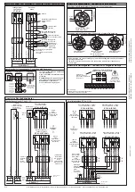
Anschluss Rauchabzugstaster
Standardanschluss RT 4x-H / -N
Fremd-
ansteuerung /
external excitation
Brandmelder /
fire detector
Arbeitskontakt /
operating contact
Alarmwiderstand
/
alarm
resistor
10k *
W
10k
W
1k
W
out
in
letzter /
last
Rauchabzugstaster /
s
moke vent button
RT 43-N (RT 42)
+Alarm
/
alarm
2
7
3
1
6
4
OK
V
V
wahlweise /
optional
out
in
erster bis
vorletzter /
first to
second
before last
Linie
/
line
–
–
1
2
10
< wahl-
weise /
>
optional
E
RM
RT
3
4
5
6
7
8
-
Kontrolle
/
control
Alarm
/
alarm
zu
/
close
RT 43-H (RT 42-H)
R
T
43-N
(R
T
42)
10k
W
Alarm
/
alarm
-
Störung
/
malfunction
2
7
8
3
1
6
4
Alarm
/
alarm
zu
/
close
RD
GN
YE
2
3
1
6
4
7
5
10k *
W
Sammelstörung
/
*
general
malfunction
* nur bei /
RT 4x-H
only at
jeweils erster
bis vorletzter
RWA-Taster /
first to
second before
last smoke vent
button each
jeweils
letzter
RWA-Taster /
every last smoke
vent button
RZN 4503-T
BMZ-
/
-
Reset
F
ACP
1
2
RM
RT 43-N (RT 42)
RT 43-N (RT 42)
-
-
2
2
7
7
3
3
1
1
6
6
4
4
1
2
3
4
5
6
7
8
RZN 4503-T
–
–
Alarm
/
alarm
Sammel-
störung /
*
general
malfunction
RM / RT
RT 43-H (RT 42-H)
RT 43-H (RT 42-H)
R
T
43-N
(R
T
42)
R
T
43-N
(R
T
42)
10k
W
10k
W
Alarm
/
alarm
Alarm
/
alarm
-
-
Störung
/
malfunction
2
2
7
7
8
8
3
3
1
1
6
6
4
4
Alarm
/
alarm
2
2
3
3
1
1
6
6
4
4
7
7
5
5
bauseitige
Rangier-
verbindung /
Shunt
connection
by customer
Parallelanschluss RT 4x-H / -N
Anschluss Antriebe und Lüftungstaster /
Connection of drives and vent buttons
MOT
Zentrale /
control panel
Mot. b
76
5
Mot. a
Überw /
.
M
M
br
bl
br
bl
Abzweigdose
am Motor /
branch box
on motor
weitere Abzweige
gleichartig schalten /
connect further
branchings alike
Abzweigdose /
branch box
- Versorgungsadern
zweigen parallel ab /
-
wird durch alle Kabel bis
zum Gruppenende durchgeschleift. /
Mot. a und Mot. b
Überwachung
- Supply wires
and
branch
off parallel
-
is looped through
all the cables up to the group end.
Mot. a
Mot. b
Monitoring
Anschluss bei Leitungsabzweig /
Connection with line branch
Anschluss Brandmelder /
Connection of fire detectors
Anschluss eines Brandmelders /
Connection of one fire detector
Anschluss mehrerer Brandmelder /
Connection of several fire detectors
Anschluss Haftmagneten /
Connection of magnetic clamps
* Bei Verwendung von Linienschaltungen mit 2-Melder-Abhängigkeit, darf der Widerstand
nicht eingesetzt werden. /
* The resistor must not be used when line connections with 2-detector dependency
are employed!
-
+
-
+
-
+
N- N+ A
K
S
Unterbrechertaster /
Interrupter button
Haftmagnet /
Magnetic clamp
Haftmagnete /
24V
(max. 200mA* Gesamtstrom /
)
Magnetic clamps
overall power
Ausgang bei
Netzausfall
spannungsfrei! /
Low tension side
in neutral position in
case of power failure!
M
Z
B
*Der maximale
Gesamtstrom darf nicht überschritten werden.
*overall power must not be exceeded
Linie /
line
-
einziger Brandmelder /
180R
1
2
3
4
5
6.
7
*
Endwiderstand
/
terminal
resistor
10K
single fire detector
Linie /
line
-
erster Brandmelder /
first fire detector
zweiter bis vorletzter
Brandmelder /
letzter Brandmelder /
last fire detector
180R
1
2
3
4
5
6.
7
*
180R
1
2
3
4
5
6.
7
*
180R
1
2
3
4
5
6.
7
*
Endwiderstand
/
terminal
resistor
10K
second to second before
last fire detector
Linie
/
line
Linie
/
line
jeweils
letzter
RWA-Taster /
every last smoke
vent button
Rauchabzugstaster /
s
moke vent button
Kontrolle
/
control
zu
/
close
Linie
/
line
Linie
/
line
+Kontrolle
/
+control
zu
/
close
Linie
/
line
Linie
/
line
* nur bei /
RT 4x-H
only at
+Alarm
/
alarm
+Kontrolle
/
+control
zu
/
close
Linie
/
line
Linie
/
line
+Alarm
/
alarm
+Kontrolle
/
+control
zu
/
close
Linie
/
line
Linie
/
line
Rauchabzugstaster 1. Strang /
s
moke vent button 1st Lane
Rauchabzugstaster 1. Strang /
s
moke vent button 1st Lane
Rauchabzugstaster 1. Strang /
s
moke vent button 1st Lane
Rauchabzugstaster 1. Strang /
s
moke vent button 1st Lane
Kontrolle
/
control
zu
/
close
Linie
/
line
Linie
/
line
Kontrolle
/
control
zu
/
close
Linie
/
line
Linie
/
line
RD
GN
RD
GN
zu
/
close
zu
/
close
RD
GN
YE
zu
/
close
RD
GN
YE
zu
/
close
Störung
/
malfunction
Kontrolle
/
control
zu
/
close
Linie
/
line
Linie
/
line
RZN 4503-T
Lüftungstaster /
vent button
Antriebe /
drives
LT 43
(-SD)
Querschnitte und Leitungsarten
siehe unten /
cross sections and type of lines,
see below
zu
/
close
–N
Aufmeldung
/
OPEN
signal
auf
/
open
erster bis vorletzter /
first to penultimate drive
LT
4
3
Aufmeldung
(wahlweise)
/
OPEN
signal
(optional)
–N
Überwachung
/
monitoring
Mot.a
Mot.b
5
6
7
1
2
3
4
LT
MOT
L
L
P
P
braun /
brown
blau /
blue
Branderkennungselement /
thermal detector
THE 4
BK
BK
OR
2x47k
W
EM 47K
letzter Antrieb /
last drive
bauseitige Abzweigdose /
branch box by customer
Antriebe mit
HS Funktion /
drives with
HS function
braun /
brown
weiss /
white
orange (-HS)
zu
/
close
auf
/
open
bauseitige Abzweigdose /
branch box by customer
Abzweigdose /
branch box
moni-
toring
Abzweigdose
am Motor /
branch box
on motor
jeweils
letzter
RWA-Taster /
every last smoke
vent button
jeweils
letzter
RWA-Taster /
every last smoke
vent button
V
V
wahlweise /
optional
jeweils erster
bis vorletzter
RWA-Taster /
first to
second before
last smoke vent
button each
Alarm
/
alarm
Alarm
/
alarm
Alarm
/
alarm


