0 degrees
30 degrees
45 degrees
More than
45 degrees
% Working
Load
100%
65%
30%
25%
2.3 Flying with AncraTrack
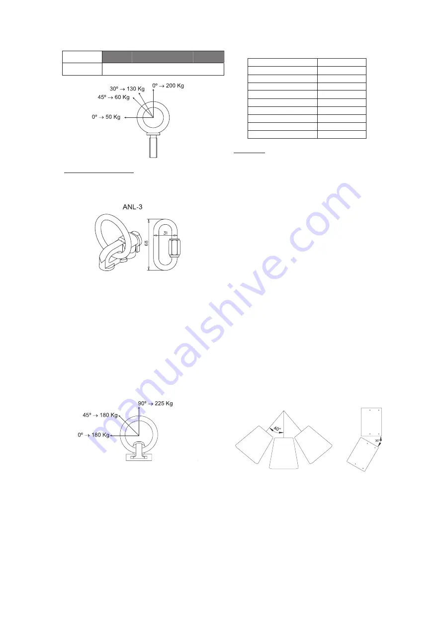
The ANL-3 set is an optional set of one double-stud
track connector with lifting ring and one carabiner.
Each ANL-3 track connector has a rated working
load of 225 kg. (500 lbs.). Each ANL-3 carabiner has a
working load of 330 kg (726 lbs.). If using other hardware,
makesureitisratedtohandletherequiredload.Always
ensure that the double-stud connector is well connected to
the track by shaking the piece firmly.
When using track based rigging it is important to
bear in mind that the rated working load is only true for a
load applied in the plane of the eye, and changes for other
angles. The drawing illustrates the concept. The table shows
the variation of the working load as a function of the load
angle (see illustration). In the case of the ANL-3 track
connector, this means that the 225 kg working load
becomes 180 kg at 90 degrees.
When using the AncraTrack, the following vertical
angles for the cabinet are obtained when connecting to the
different track positions. The position relates to the hole
number above which the ring is found. Position 1 is the
closest to the front of the enclosure. Note that positions 1
and 9 mean that only one connector stud attaches to the
track, as opposed to two for all angles in between. Negative
angles denote downward pitch. Positive angles denote
upward pitch.
Track hole number
Vertical angle
1
+11.8º
2
+8.4º
3 +4.9º
4 +1.5º
5
-1.4º
6 -4.8º
7 -8.4º
8
-11.7º
9 -15.1º
2.4 Arraying
Ideally, only a super-high powered variable
coverage speaker would be used per channel for covering
any room. Not achievable in real life, one must resort to
arrays or clusters.
Speakers are arrayed for two reasons:
-
To extend the coverage of a system that has too narrow
directivity.
-
To increase the sound pressure level.
The tables that follow offer directivity information
for different tight-packed array combinations, separately for
horizontal and vertical. Coverage angle, directivity index (an
expression of the directivity of an array, the more directive
the higher) and on-axis SPL (relative to a single box) results
are provided.
For every model, results are provided for a number
of array boxes from 1 to 5, with splay angles from 0 to 50
degrees in 10-degree intervals. Boxes are tight packed.
Results are for the 500 to 8k Hz band, except for subs,
where a one octave 100 Hz band is used.
NA
The results are calculated from polars with two degree angular and 1/24th octave
frequency resolution. Active mode was used in active/passive boxes. AUTOPOL, a
platform consisting of custom and customised hardware and software, was used for
automated high-resolution array predictions. Predictions for the 500-8k Hz band may
overestimate the coverage angles, which can reach lower values at specific
frequencies.
Example.
A 3x2 ST-1510 array (3 columns and 2 rows)
with 40-degree horizontal and 30 degree vertical splay
(shown on the illustration).
To find out the coverage of such array, we go to
the horizontal section of the ST-1510 table and look for the
40º/3x cells, and the 30º/x2 cells on the vertical section. The
results (cells have a grey background) show coverage
angles of 165 degrees horizontal and 95 degrees vertical,
and an on-axis SPL of +1 dB (horizontal) and +2 dB
(vertical) for a total on-axis level of +2 dB (0 dB horizontal
+ 2 dB vertical) above the level for a single box.
13
Manual del Usuario /
User’s Manual
Sound Touring
/
Summary of Contents for ST-1510
Page 2: ...ST...
Page 6: ...Manual del Usuario User s Manual Sound Touring...
Page 8: ...Manual del Usuario User s Manual Sound Touring...
Page 14: ...Manual del Usuario User s Manual Sound Touring...
Page 16: ...Manual del Usuario User s Manual Sound Touring...
Page 22: ...Manual del Usuario User s Manual Sound Touring...
Page 23: ......


