


ROBOT . HEAD to TOE
Product User’s Manual –
SD02C
3. PRODUCT SPECIFICATION AND LIMITATIONS
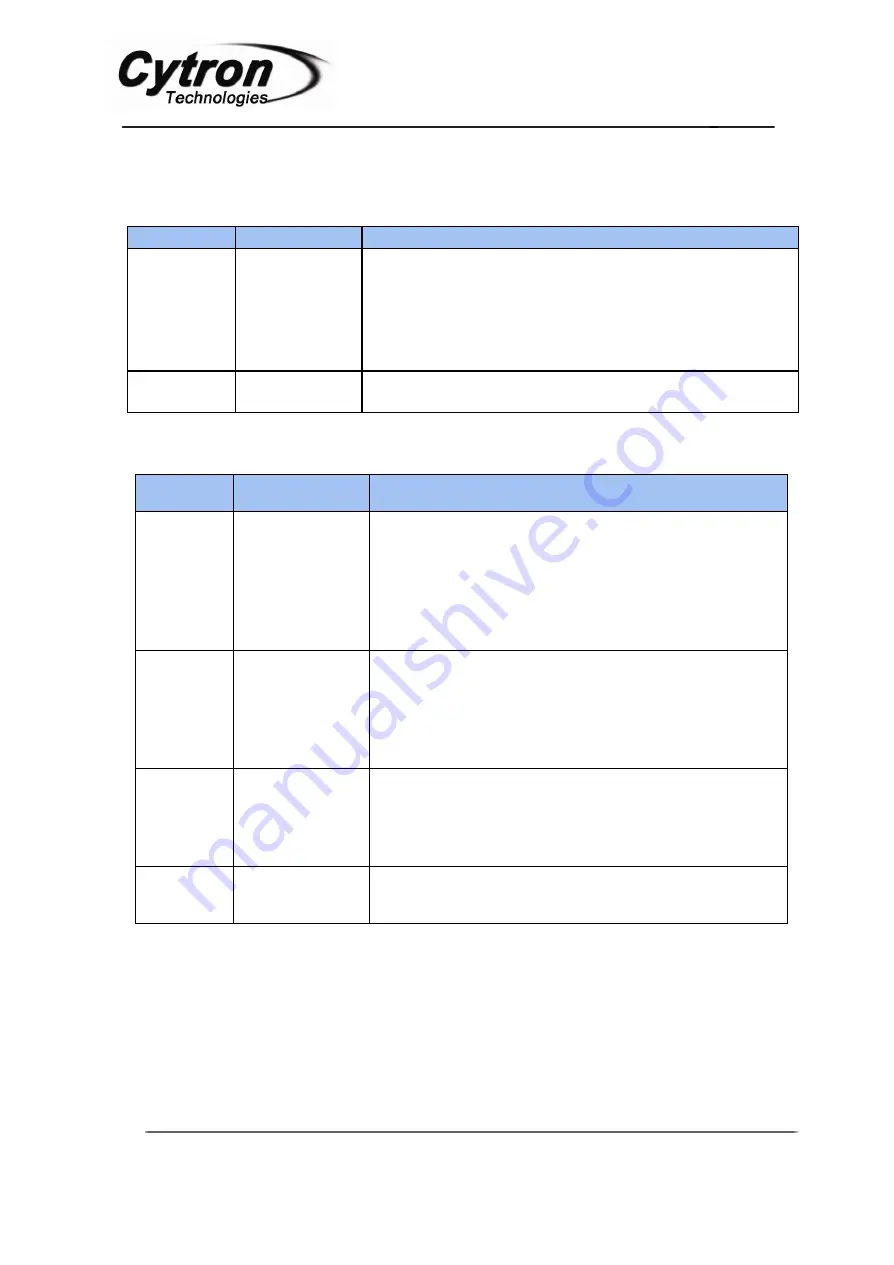
Power Input Pins Function Description
Label
Definition
Function
VM
Motor Supply
Voltage
VM is one of SD02C power sources. VM will supplies power
to both stepper motor and SD02C circuit. Although SD02C
provides protection against wrong polarity for this input,
user must ensure the voltage and polarity of connection are
correct before providing the power so that SD02C can function
correctly.
GND
System Ground
Common ground for both logic operation and stepper motor
power source.
*If power is connect correctly, the PWR LED should light up.
Signal Input Pins Function Description
Label
Definition
Function
DIR
Stepper Motor
Rotating
Direction
Input Pin
Input for stepper motor to rotate CW (clockwise) or CCW
(counterclockwise). This pin is TTL/CMOS logic (5V and
0V). The direction is depends on the connection sequence
of stepper motor wires to SD02C. For example:
DIR = 0V CW
DIR = 5V CCW
EN
Stepper Driver
Enable Pin
Input pin to enable SD02C. This pin is TTL/CMOS logic
(5V and 0V). 5V will enable the motor driver further hold
the shaft of stepper motor while 0V will disable the motor
driver and release the shaft of the stepper motor. By
default, the driver is disabled for power saving.
PULSE
Stepping Pulse
Input Pin
Input to drive the stepper motor. This pin is
TTL/CMOS logic (5V and 0V). Each pulse (logic
change from 0 to 1) will drive the stepper motor 1step.
SD02C has 2/4/8 micro stepping.
GND
System Ground
Common ground for both logic operation and stepper motor
power source.
Created by Cytron Technologies Sdn. Bhd. – All Rights Reserved


