Product User’s Manual – ESPWiFi Shield Rev2.0
7.0 GETTING STARTED
This section will show examples of using ESPWiFi Shield together with Arduino Board to
1) perform AT test basic module testing by sending AT commands
2) create a simple WiFi server
7.1 AT Test
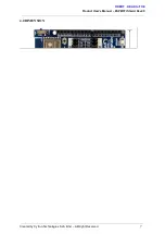
1. Stack ESPWiFi Shield onto compatible Arduino Board. For this example, Arduino
Uno is used.
2. Select USB for both RX and TX pins.
**Note: This setting is only for entering AT
command.
3. Make sure the slide switch is switched to RUN mode.
4.
**Note:
For AT Test, connect RST pin to GND using jumper wire. (Another
alternative, upload an empty sketch to Arduino main board before stacking
ESPWiFi Shield onto Arduino board.)
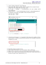
5. Connect Arduino board to PC using USB cable.
6. Open Arduino IDE. Determine which COM port Arduino Uno is connected to and
configure the port settings under menu Tools > Port.
7. Open and set up Arduino Serial Monitor with settings below.
● 9600 Baud
● Both NL & CR
8. Figure below shows sending “AT” using Arduino Serial Monitor. If the result returns
“OK”, it means you have successfully communicate with the ESP8266 module on
ESPWiFi Shield, AT test is successful. User can also try out other AT commands like
AT+GMR, etc.
Created by Cytron Technologies Sdn. Bhd. – All Right Reserved
10


