CYRUS DVD6 TECHNICAL DESCRIPTION
© Cyrus Electronics Ltd Dec 2003
Cyrus DVD6 Service Manual Issue 1
8
Disc reading/decoder module
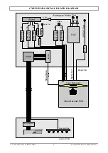
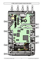
A disc-reading module is at the heart of the DVD6. The module includes a twin laser mechanism
and a decoder PCB. The decoder PCB performs a number of functions, decoding video and audio
data from the DVD and includes the firmware for disc navigation, on-screen menus etc. The
connections to/from the module include power supplies, analogue video output, digital audio output
and control/status signals to/from the microprocessor control system on the main board. The
decoder PCB is specific to the DVD6 and is not a serviceable item. Depending on availability,
Cyrus UK may supply complete modules or decoder boards and lasers separately.
The specification of replacement modules has changed slightly in the life of the DVD6. The original
module used (version ASD1) is not available for replacement, later specification replacements may
be used, but are not directly interchangeable, causing corrupt characters on the display and changes
to the on-screen menu. Changes will be required to the product software and possibly IC404. The
replacement module may also change the functionality of the player slightly. A handbook
addendum will be available to list the changes in functions.
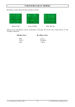
The module version is identified by a Green circle label on the PCB (version ASD-1/2B), a label
with the wording ‘Module SD3.0’ on the PCB (version SD3.0) or neither of these labels (version
ASD-1). Refer to Cyrus Service department with the module version, serial number and software
version of the DVD6 when a replacement module or PCB is required.
Module versions are described in more detail in Technical Bulletins available from the Cyrus
Spares department.
Microprocessor control system
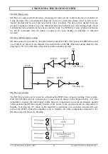
System control for the player is provided by IC403. This IC accepts commands from the IR handset,
front panel keys, or MC Bus from another unit, and translates them into instructions for the
mechanism. The communication interface to the mechanism is via a parallel bus to IC404, then to
the mechanism via a serial bus. Status information is returned back through this IC from the
mechanism. IC405 controls the data direction.
IC403 is reset by IC401 when power is first applied. IC401 constantly senses the condition of the
+5V power supply to IC403, causing a system reset if this voltage drops below an acceptable level
(4.3V). After a system reset the DVD6 will set to Standby.
The software contained in IC403 is electrically programmed into internal flash memory when the
DVD6 is manufactured. This software may be updated by a service department as later versions are
released by connecting a PC with the new software via the Cyrus Flash-Programming Interface to
the 10 pin programming connector on the main PCB. If IC403 is replaced for any reason new
software must be installed after the replacement IC is fitted. The software version may be checked
from the front panel of the DVD6 by using the following key sequence -
1. Connect power to the DVD6 and set to Standby (power light red).
2. Press and hold the Eject key.
3. The software version and release date will be shown on the display.
Refer to the section ‘Control Software’ in this Service Manual for instructions in the use of the
Flash-Programming Interface.
IC404 is also a programmed device. The software version number is shown on the IC label. When
replacing this IC it is important to order the original software version by quoting the number on the
label. Under certain circumstances a new software version may be required for IC404 (decoder PCB
replacement etc). This software is not programmable by a service department and the IC will
require replacement with a new version from the Cyrus spares department.

