


Page of
24
31
HHR-4X66 Single-lane Kits - Field Installation
(cont.)
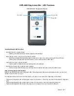
D. Testing the Handheld Reader-to-Base Unit connection (HHR-8300)
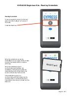
1. Power on the reader. The blue LED will be on and solid when the reader is powered on. The blue LED will changed
to flashing when the reader is communicating with the Base Unit.
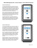
2. Present a valid credential to the reader. The red and green LEDs will flash once, indicating the credential has been
read. Verify that the access controller has received the read on the Wiegand port Board A is connected to. Observe
the Access Granted Response; the green LED will be flashing, the reader will vibrate, and the reader will emit a high
pitched tone. The Access Granted Response will last as long as the LED In pin on Board A is activated.
3. Present an invalid credential to the reader. The red and green LEDs will flash once, indicating the credential has
been read. Verify that the access controller has received the read on the Wiegand port Board A is connected to.
Observe the Access Denied Response; the red LED will be flashing, the reader will vibrate in a pulsing pattern, and
the reader will emit a low pitched tone. The Access Denied Response will last as long as the Relay 1 In pin on Board
A is activated.
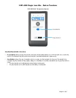
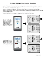
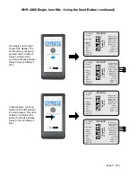
4. Press and release the Vend button. Verify that Relay 3 on Board A has changed state. Observe that the duress
alarm activates, the door/gate opens, etc. A volt meter in continuity mode can also be used determine the state of
the relay. When the Vend Button is pressed, there will be continuity between Relay 3 COM and Relay 3 N.O. for as
long as the Vend Button is held down.
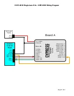
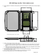
E. Connecting the HHR-8400 Base Unit to the access controller
1. To connect the Base Unit to the access controller, 2 separate Wiegand ports must be available.
2. Connecting Board A to the access controller:
A. Wiegand Data: Connect Data 0, Data 1, and a common ground to the one Wiegand port on the access
controller.
B. Access Granted Response: Connect an active low digital output to the LED In pin. Alternatively, a dry contact
can be connected to the LED In pin and Ground. Make sure the output connected to the LED In pin is
configured to activate for at least one second when a valid credential is received on this Wiegand port.
C. Access Denied Response: Connect an active low digital output to the Relay 1 In pin. Alternatively, a dry contact
can be connected to the Relay 1 In pin and Ground. Make sure the output connected to the Relay 1 In pin is
configured to activate for at least one second when an invalid credential is received on this Wiegand port.
D. Vend Feature: Connect Relay 3 COM and Relay 3 N.O. (normally open) to the access controller. This relay
output can be used to control a door, a gate, or other equipment.
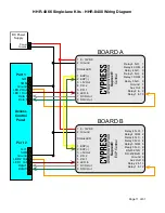
6. Connecting Board B to the access controller:
A. Wiegand Data: connect Data 0, Data 1, and a common ground to another Wiegand port on the access
controller.
B. Access Granted Response: connect an active low digital output to the LED In pin. Alternatively, a dry contact
can be connected to the LED In pin and Ground. Make sure the output connected to the LED In pin is
configured to activate for at least one second when a valid credential is received on this Wiegand port.
C. Access Denied Response: Connect an active low digital output to the Relay 1 In pin. Alternatively, a dry contact
can be connected to the Relay 1 In pin and Ground. Make sure the output connected to the Relay 1 In pin is
configured to activate for at least one second when an invalid credential is received on this Wiegand port.
D. Vend Feature: connect Relay 3 COM and Relay 3 N.O. (normally open) to the access controller. This relay output
can be used to control a door, a gate, or other equipment.
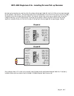
7. Board A and Board B need to be connected. Connect EXP(+) on Board A to EXP(+) on Board B. Connect EXP(-) on
Board A to EXP(-) to Board B.
8. Use a power supply that can supply 8-16Vdc @ 600mA. Both Board A and Board B need to have a power
connection, and each require 300 mA.


