Liquid-Tolerant Design Considerations
CY8C20xx7/S CapSense
®
Design Guide
Doc. No. 001-78329 Rev. *E
60
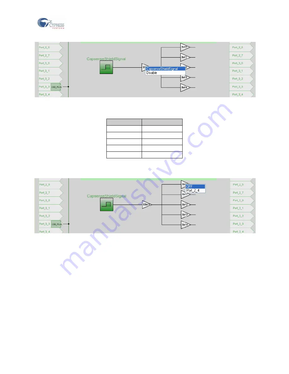
Figure 6-4. Enabling CapsenseShieldSignal from GUI
Step 2:
Route the shield electrode out to the shield pin.
There are five possible shield drive buffers, labeled Buf 0 through Buf 4; their mapping is shown in the following table.
Shield Buffer
Output Port Pin
Buf 0
Port_2_4
Buf 1
Port_2_2
Buf 2
Port_0_2
Buf 3
Port_0_0
Buf 4
Port_1_2
The shield drive buffers are OFF by default; select the desired shield drive buffer.
Buf 0 such that the shield signal is driven out on Port_2_4.
Figure 6-5. Schematic View of Output Select
Step 3:
Choose polarity of the shield signal.
There are two polarity choices, see
Normal Mode (default): Shield driver signal in phase with sensor scan signal
Reverse Polarity: Shield driver signal 180° out of phase with sensor scan signal
Normal Mode shows the best performance in liquid-tolerant designs.


