Kit Operation
CY4541 EZ-
PD™ CCG4 Evaluation Kit Guide, Doc. No. 002-10353 Rev. *E
45
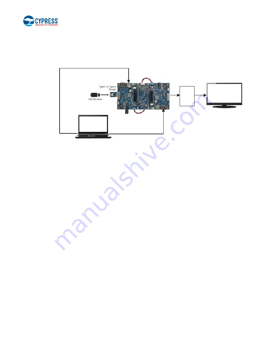
3. Connect the boards, cables, and dongles as shown in
Ensure that the monitor supports a DisplayPort, HDMI,
VGA, or DVA interface.
Figure 32. Setup of the DisplayPort Demo
Display
Port
Cable
Type-C
to DP
Dongle
DisplayPort cable connected
to CCG EVK Base Board 2
J4
J3
Type-C Port 1
Type-C Port 2
USB 3.0 Type-A to Type-B
Cable connected to
CCG EVK Base Board 1
J2
J3
USB
DP
DC Power Adapter
connected to
CCG EVK Base Board 1
4. Ensure that the
“Extended Display” feature is enabled in the USB host PC. For Windows users, this feature can be enabled
by clicking
Extended Display
, available at “Control Panel\All Control Panel Items\Display\Connect to a Projector” window.
For Linux or Mac users, this feature can be enabled by checking the
Mirror image
option,
available at “System Preferences
(or Settings)\
Display”.
5. Observe that the DisplayPort video is transmitted from the host (PC) to the display monitor through Type-C port 2. This
demonstrates the CCG4’s capability to control the transfer of DisplayPort data over the Type-C interface.
6. SuperSpeed USB data transfer can be performed simultaneously by connecting USB Type-C to Type-A adapter and USB
pen-drive to Type-C port 1 as shown in
. Also, the connection of USB 3.0 Type-A to Type-B Cable to the
SuperSpeed USB Type-B connector (J2) of CCG EVK base board 1 is mandatory when the USB pen drive is connected
to Type-C port 1.
6.3.3 Running the Dual DisplayPort Demo
In this demo, CCG4 delivers a DisplayPort video from the host (PC) to display monitors connected to Type-C port 1 and Type-C
port 2 using a Display Splitter board (not provided with the kit; refer to the
Splitter board is not available, then the Dual DisplayPort demo can be performed by connecting two PCs having DisplayPort
outputs, as shown in
. In this case, the DisplayPort output of PC 1 is connected to the DisplayPort connector of CCG
EVK base board 1 and the DisplayPort output of PC 2 is connected to the DisplayPort connector of CCG EVK base board 2.
1. Use the default jumper settings shown in
to configure the CY4541 EZ-PD CCG4 EVK.
2. Connection details:
▪
Remove wires from the power output header (J7) on CCG EVK base board 1 and CCG EVK base board 2. Connect
wires between the power input headers (J12) of both the CCG EVK base boards as shown in
. Note that this is
the same setup as used in the DRP and SuperSpeed USB demo shown in
▪
Connect the DC power adapter (provided with the kit) to the DC power jack (J1) of either of the CCG EVK base boards.
LED1 (Green) on the CY4541 CCG4 daughter card and on both the CCG EVK base boards glow to indicate that the
board is powered. Also, LED2 (Orange) on the CCG EVK base board, connected to Type-C port 1 of the CY4541 CCG4
daughter card, blinks continuously.


