© 2017 Cypress Solutions
Manual: CTM ONE (Revision 1.0)
7
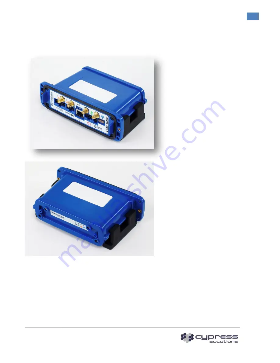
Product Overview
2
Page 1: ...CTM ONE MANUAL Model CTM ONE M PLUS Revision Revision 1 0 3066 Beta Avenue Burnaby B C V5G 4K4 Phone 604 294 4465 Fax 604 294 4471 support cypress bc ca...
Page 2: ...2017 Cypress Solutions Manual CTM ONE Revision 1 0 2 Revision Control Revision Control Description Initials Rev Date Initial Release mm 1 0 26 FEB 2019...
Page 3: ...ts GPIO Serial 8 3 3 Auxilliary and IButton 8 3 4 USB OTG On The Go port 8 3 5 CAN Bus port 8 3 6 Locking 3 Wire power connector with ignition sense 9 3 7 Multiple RF connectors SMA RP SMA 9 4 SIM Car...
Page 4: ...232 Serial Access 23 6 4 Login 23 6 5 Web Interface 24 6 5 1 Dashboard 24 6 5 2 System Database 24 6 5 3 Installer 25 6 5 4 Firmware 25 6 5 5 Change Password 25 6 5 6 Configuration 26 7 Additional Fea...
Page 5: ...gulatory approval status to become invalidated thereby voiding your authority to use the product The CTM ONE wireless data device contains a wireless module approved under FCC CFR 47 part 2 1091 and I...
Page 6: ...n for help 1 4 Electromagnetic Interference EMI Canada Information This digital apparatus does not exceed the class B limits for radio noise emissions from digital apparatus as set out in the interfer...
Page 7: ...2017 Cypress Solutions Manual CTM ONE Revision 1 0 7 Product Overview 2 Product Overview...
Page 8: ...tion interface Inputs x 4 2 differential Outputs x 4 Console Command Line Interface access PAD host interface 1 available Virtual Serial Line replacement MODBUS host interface MODBUS interface Various...
Page 9: ...M ONE supports two 2FF style SIM cards One or two SIMS can be installed For single SIM card installation we recommend use the upper sot of the dual SIM holder the UPPER Slot is the slot furthest away...
Page 10: ...hat the gasket is in place when the Battery cover is reinstalled and tighten screws in a x cross pattern until snug for optimal weather tight seal Do not overtighten recommended torque value 4 5 in lb...
Page 11: ...s may need to be used to provide adequate Cellular Wi Fi GNSS operation Optimal in vehicle mounting locations includes areas that have clear visibility of the sky such as under dash under window locat...
Page 12: ...ket that has four 5mm mounting holes suitable for 10 screws Take care not to over tighten these screws and damage the bracket Once this has been installed in the required location clip the CTM ONE int...
Page 13: ...43030 Crimp Terminals 20 24 AWG The CAN interface is used primarily to interface to Vehicle sub systems that support CAN communications This includes all small and light duty vehicles manufactured in...
Page 14: ...ector Molex Part Number Description 43025 0400 Receptacle housing 43030 Crimp Terminals 20 24 AWG When a compatible vehicle interface is not available or not preferred the CTM can be connected with a...
Page 15: ...this line using its ignition sense features When the ignition line is wired the CTM ONE does not completely shut down a small amount of power is used 1 2mW 40 mW to monitor the status of various input...
Page 16: ...cm 8 The decision to use external antennas should be made based on performance evaluation of how the product performs when placed in the desired location within the vehicle or fixed site 5 5 1 Cellula...
Page 17: ...NE s Ethernet port and the other end into the LAN device PC or Ethernet peripheral The Ethernet port is compatible with 10Base T or 100Base T connection types The Ethernet port support auto MDI MDIX m...
Page 18: ...und of the 14 pins configured as Data Communication Equipment DCE RS485 uses two pins Serial data ports on most computer equipment are configured as Data Terminal Equipment DTE In some cases it may be...
Page 19: ...e all input and outputs have transient protection The I O port provides for the control of 4 external devices and for monitoring 4 external inputs GPIO Block Pin Signal Name 1 INPUT1 Single Ended Inpu...
Page 20: ...G Note that the OUT GND connection is connected to the CTM ONE s supply ground 5 8 2 GPIO Input Connection The 4 inputs may be configured in the CTM ONE for monitoring a digital DC voltage state or an...
Page 21: ...ample of Digital Input wiring For analog voltage monitoring the measurement range is 0 to 10 volts with 10mV resolution The input can withstand up to 36 volts Note that the IN GND connection is refere...
Page 22: ...0 connector Molex Part Number Description 43025 1000 Receptacle housing 43030 Crimp Terminals 20 24 AWG The auxiliary connection enables communication with Maxim iButton Devices and provides the abili...
Page 23: ...ssword is CypressAccess CTM ONE Web interface is accessible by opening a browser to http 192 168 2 1 6 2 LAN0 Access When physically connected using an Ethernet cable the CTM ONE Web interface is acce...
Page 24: ...rface The Web GUI is designed to be an intuitive system to view and change device settings 6 5 1 Dashboard The Dashboard shows general system settings 6 5 2 System Database The system database is a se...
Page 25: ...A page typically used by installers to verify basic device functionality and available vehicle ECU CAN Bus Data 6 5 4 Firmware A page to locally install device firmware with a sub page for monitoring...
Page 26: ...ual CTM ONE Revision 1 0 26 Accessing the CTM ONE 6 5 6 Configuration The Configuration page has folders that can be expanded to provide configuration details Note the Configuration page shown may var...
Page 27: ...he device will spend most of its time in this mode triggers such as timer or input state change will bring the device out of this mode into Operating System mode Operating system 25 30mA Linux is oper...
Page 28: ...by monitoring events such as Acceleration GPS location on board Geo Fence Time Speed Temperature Voltage Input events 7 2 Power Consumption The power consumption of the CTM ONE gateway will depend on...
Page 29: ...Off Power Power status Full operating mode running of DC input Standby Device has no power SIM SIM Status Green using SIM1 Red using SIM2 No SIM installed Cellular connectivity disabled Cellular Indic...
Page 30: ...d by default to auto connect to a cellular network If the CTM ONE determines that communication with the internal cellular radio module or device is not working it will attempt to reset the communicat...
Page 31: ...ions Manual CTM ONE Revision 1 0 31 General Troubleshooting Operation Technical Support Cypress Solutions Service Support Group 1 844 462 9773 or 778 372 4603 5 00am to 5 00pm PST support cypress bc c...