


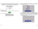


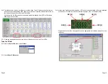


6.10. To assign an LED to a CapSense slider segment, simply click on the yellow box of the
CapSense slider segment you want to assign to LED G0. For LED driver G0, select the
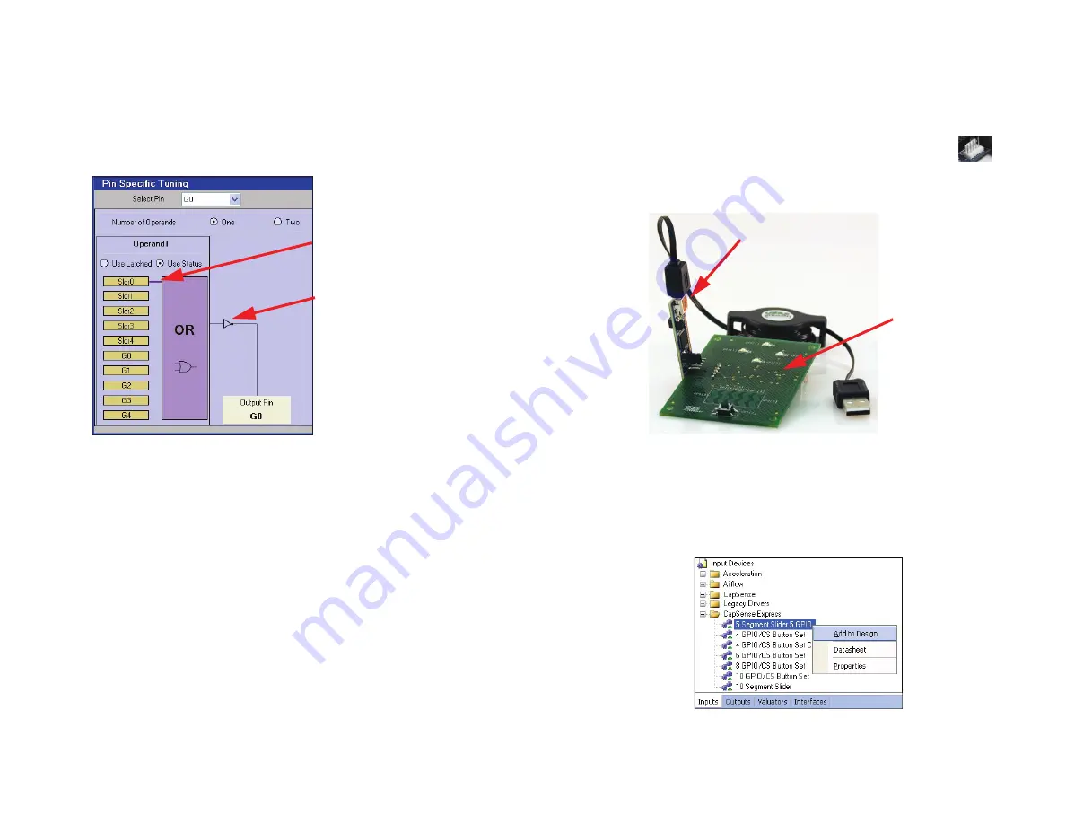
CapSense slider segment Sldr0. A small line will then connect C0 to the purple OR box.
To have the LED turn on when the slider segment is touched, click the little box to the right
of the purple OR box. This will change the square to an invert symbol.
Invert Symbol
Connecting Line
Default = LED Off
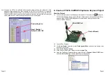
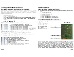
6. Create a CY3218-CAPEXP2 CapSense Express Project
Start the Project
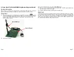
6.1. Connect your computer to the CapSense test board I
2
C Connector (J5)
using the
CY3240-I2USB Bridge Board and a USB cable. When connected correctly, the USB con-
nector on the CY3240-I2USB Bridge Board is visible when viewing the front of the
CY3218-CAPEXP2 board.
6.2. Launch PSoc Express.
6.3. Click
New Project
, name the project
FiveSegmentSlider
, and save the design in the
location of your choice.
6.4. Select
View
>
Driver Catalog
.
6.5. At the bottom of the Driver Catalog, select the
Inputs Tab
.
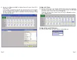
6.6. Open the CapSense Express directory, right-click the
5 Segment Slider 5 GPIO
driver,
and select
Add to Design
. The Add Input Driver window opens.
Front of Board
Mini USB Port
Page 12
Page 9


