

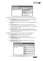
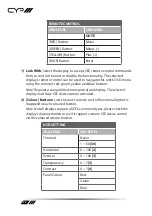
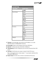
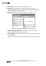
9
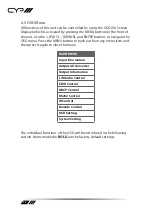
6. OPERATION CONTROLS AND FUNCTIONS
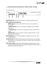
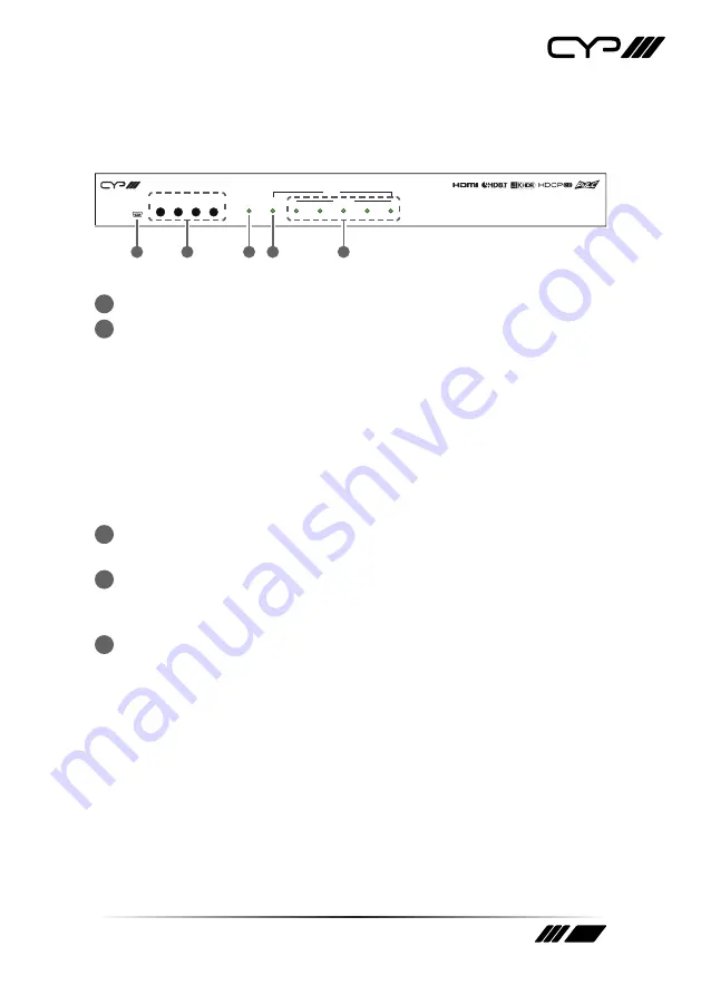
6.1 Front Panel
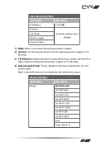
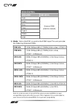
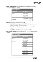
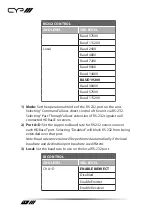
SERVICE
MENU
+
ENTER
POWER
INPUT
OUTPUT
SYNC
A
B
C
D
E
-
PUV-1H4HPL-AVLC
1
2
3
4
5
1
SERVICE Port:
This port is reserved for firmware update use only.
2
CONTROL BUTTON BLOCK
MENU Button:
Press to enter the OSD menu, or to back out from
menu items.
- (MINUS) Button:
Press to move down or adjust selections within
OSD menus.
+ (PLUS) Button:
Press to move up or adjust selections within OSD
menus.
ENTER Button:
Press to confirm a selection within the OSD or to go
deeper into a menu item.
3
POWER LED:
This LED will illuminate to indicate the unit is on and
receiving power.
4
INPUT LED:
This LED will illuminate to indicate that a live source has
been detected on the input port. When no source is detected the LED
will remain off.
5
OUTPUT LEDs:
These LEDs will illuminate to indicate when a valid
sink has been detected on the associated output port. When no sink is
detected the LED will remain off.
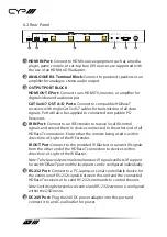
Summary of Contents for PUV-1H4HPL-AVLC
Page 1: ...PUV 1H4HPL AVLC 1x4 HDBaseT Splitter with AVLC OPERATION MANUAL ...
Page 2: ......
Page 44: ......
Page 45: ......