


(8). Specifications
Computer input
Max computer input resolution
Computer input connector type
Computer input signal level
Video inputs
Video standard
Video input connectors
Scaled output resolutions
Scaled output vertical refresh rates &
Horizontal scan rates
Manual control
RS-232 control
IR remote control
Video adjustments
Weight
Dimensions
Power source
RGB with HV Sync
1280x1024
HD 15 Female
RGB @ 0.7V, H&V Sync @ TTL
Composite Video @ 1 Vp-p 75 ohm
S-Video @ 1 Vp-p 75 ohm
YPbPr Y : 1 Vpp 75 ohm
PbPr : 0.7 Vp-p 75 ohm
NTSC 3.58, PAL B/D/G/I
Composite video on BNC
S-Video on 4-pin Mini-DIN
Component on BNC
Pixels Format Scan
VGA 640 x 480
SVGA 800 x 600
XGA 1024 x 768
SXGA 1280 x 1024
WVGA 848 x 480
WXGA 1280x768
1360x768 1360x768
UXGA 1600x1200
Output resolution Vert. (Hz) Hori. (Hz)
59.94
31.469
VGA
SVGA
XGA
SXGA
WVGA
WXGA
1360X768
UXGA
60.320
37.880
60.000
48.360
60.020
60.00
59.99
60.02
60.0
63.981
31.020
47.396
47.712
75.000
Front panel buttons
Via rear panel DB9F connector
Yes
Brightness, Contrast, Color Saturation, Hue (NTSC), Detail1
1Kg
204(D)x 154 (W) x 46(H)mm
100~240VAC to DC 12V/1A Desktop switching adaptor
RGBHV
RGBHV
RGBHV
RGBHV
RGBHV
RGBHV
RGBHV
RGBHV
Progressive
Progressive
Progressive
Progressive
Progressive
Progressive
Progressive
Progressive
9
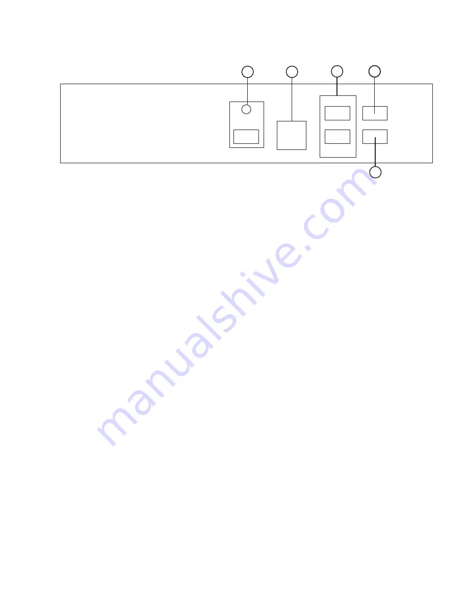
(4). Connecting the hardware
The video scaler is controlled via front panel push buttons or remote control and its
status is indicated by OSD display. The front panel controls are shown below.
Front Panel
2
1. Mode: Press the button repeatedly will toggle through the following adjust controls:
Source
Resolution
Aspect
3D Enhance
Digital NR
Sources....
Source mode: While under this mode, press
or
button to choose your
desired input source from Video, S-Video, Component or PC inputs.
Resolution mode: Press
or
button to choose output resolution
from 640 x 480(VGA), 800 x 600 (SVGA), 1024 x 768(XGA),
1280 x 1024(SXGA), WVGA, WXGA, 1360x768 or UXGA PC outputs.
Aspect mode: Press
or
to choose between Standard,16:9 or 4:3 aspect ratio.
3D Enhance mode: To turn on or off the 3D comb filter function.
When VCR or non-standard video source is connected to the
input the output picture may be jittering. If this occurs, please
turn off the 3D Enhance function.
Digital NR mode: To turn on or turn off the digital noise reduction function.
11
3
4
5
2
Front Panel
Power
Picture
Mode
CSC-210
VID/PC/HD to UXGA SCALER
(4). Connecting the hardware
2. Picture: Press the button to toggle through picture adjust parameters as follows:
Contrast
Bright
Color
Hue
Detail
Contrast
Contrast: Press
or
to adjust contrast level. The range of adjustment is 0~63.
Factory default value is 58.
Bright: Press
or
to adjust Brightness level. The range of adjustment is 0~63.
Factory default value is 31.
Color: Press
or
to adjust color level. The range of adjustment is 0~63.
Factory default value is 31.
Hue: Press
or
to adjust NTSC hue level. The range of adjustment is 0~63.
Factory default value is 31.
Detail: Press
or
to adjust detail level.
The range of adjustment is 0~63. Factory default is 31.
3.
,
: Press to toggle through various adjust controls or to alter setting value.
4. IR Sensor: Infrared remote control sensor.
5. Power and LED button: Press once to power on the unit, press again to turn off.
Note:
* Under picture adjust mode, press
and
simutaneously will revert the selected
parameter back to factory preset value. Press both buttons for over 5 seconds
will revert all picture parameters back to their factory preset values.
* You can use RS-232 to lockout the front panel controls. To lift this lockout
and revert all parameters back to factory preset value, please press"mode"
and "picture" buttons simultaneously for over 10 seconds.
6. Front Panel Lockout- Under certain circumstances it may be desirable to disable
the front panel controls. For example, to prevent unauthorized
or accidental changes to the setting while the unit is in use.
To disable the front panel controls use RS-232 to set the
front panel lockout to ON position.
3
(6). Remote Control
1. Power: Power ON/OFF button.
2. Display: Press the button to enable or disable the on screen display
of the resolution information.
3. C-Video: Press the button to select composite video as input source.
4. S-Video: Press the button to select S-Video as input source.
5. YPbPr: Press the button to select component video as input source.
6. PC: Press the button to select PC as input source.
7. VGA: Press the button to select 640 x 480 as output resolution.
8. SVGA: Press the button to select 800 x 600 as output resolution.
9. XGA: Press the button to select 1024 x 768 as output resolution.
10. SXGA: Press the button to select 1280 x 1024 as output resolution.
11. WVGA: Press the button to select 848x480 as output resolution.
12. WXGA: Press the button to select 1280x768 as output resolution.
13. 1360x768: Press the button to select 1360 x 768 as output resolution.
14. UXGA: Press the button to select 1600x1200 as output resolution.
15. Aspect ratio: Press the button to switch between Standard,
16:9 or 4:3 aspect ratio.
16 IR-Set: When front panel is locked out by RS-232, Press this button for
over 15 seconds will lift the lock out.
17. 3D: Press to turn ON/OFF the 3D enhance.
18. NR: Press to turn ON/OFF digital noise reduction.
19. Mode: Same as "mode" button on front panel.
press to toggle through
Source
Resolution
Aspect
3D Enhance
Digital NR
Source
20. Picture: Same as picture button on
front panel. Press to toggle
through Contrast
Bright
Color
Hue
Detail
Contrast
21. Reset: Press this button will revert picture
adjust back to factory preset value.
6
2
9
11
1
3
4
5
6
7
8
10
13
12
16
17
19
18
20
21
15
14
Front Panel
WVGA
UXGA
YPbPr
1360x768
WXGA
CR-24
4
(
5
)
. Connecting and Installation
(
4
)
. Connecting the hardware
5
DC Adaptor
Rear Panel
1 . Composite Video input: Use a composite video cable to connect the composite
video output of the source equipment to the connector
labeled " Video" on the back of the Video Scaler.
2 . S-Video input: Use a S-Video cable to connect the S-Video output of the source
video equipment to the connector labeled " S-Video" on the back
of the Video Scaler.
S-Video provides improved performance over Composite Video
and is recommended over composite.
3 . YCbCr/YPbPr input: Use the component cable to connect the component
output of the source video equipment to the connectors
labeled YCbCr/YPbPr on the back of the video scaler.
4 . PC input: Connect the source computer's VGA output signal to the HD 15
connector labeled "PC In" on the back of the Video Scaler.
5 . PC output: Use the HD-15 cable to connect the output to the PC input of your
display monitor.
6 . RS232: 9-pin D-sub connector for connecting to your PC or other control console
for remote control.
7 . DC power jack: 12V 1A DC power input.
2
1
3
Rear Panel
4
5
7
6
Control In
S-VIDEO
VIDEO
Y
Cb/Pb
Cr/Pr
INPUT
PC IN
RGB
DC 12V
+
RS-232
OUTPUT
S-VIDEO
VIDEO
Y
Cb/Pb
Cr/Pr
INPUT
PC IN
RGB
DC 12V
+
RS-232
OUTPUT
PC Monitor
or


