background image

DRAFT

5

3.5 ADJUST

AUDIO

FOLLOW

AUTO / WIPE

START

ON


ADJUST

DEMO

ADJUST

SCAN


BACK

COLOR


MOSAIC

VIDEO/AUDIO
MIXER


AUDIO

FOLLOW

AUTO / W PE

START

ON

NPUT A

MAX

MIN

NPUT B

MAX

MIN

AUX

MAX

MIN

M C

MAX

MIN

MAX

M N

AUDIO MIXER

MODE CONTROL

KEY

M X

P P

COLOR

WIPE

EDGE

FUNCT ONS

/4

1/3

1/2

MULTI

REVERSE

ONE-WAY

B KEY 1 2

L KEY 1 2

1/4

1 2

  SOURCE

1/3

  SOURCE

ADJUST

DEMO

AD UST

SCAN

V DEO SOURCE SELECT

BACK

COLOR

SD  NPUT 2

SD  NPUT 1

HD  NPUT 2

HD  NPUT 1

HDMI 2

HDMI 1

B

A

DIGITAL EFFECTS

ST LL

NEGATIVE

PAINT

MOS

C

ON

A

B

-15

L

AUDIO
LEVEL

R

dB

dB

-10

5

-3

+3

+4

+2

0

+1

-1

-15

-10

5

-3

+3

+4

+2

0

+1

-1

V DEO/AUD O
MIXER

HD AV EFFECTS PROCESSOR

TIME

MIN

MAX

POS TION

28

29

30

28


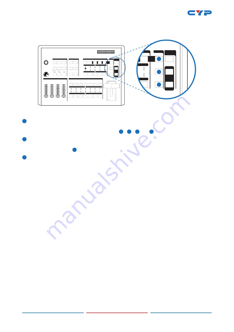
Adjust button

  When LED switched off, the SDP review output side will show AB-bus / output source and output 

format. When LED illuminate, the suer can press 

19

 / 

20

 / 

21

 and 

22

 buttons to adjust the values.

29


DEMO button

  When LED illuminate, the auto DEMO will switch to ON and the system will auto sequence Demo 

96 wipe patterns, press 

1

 TIME button to adjust the auto sequence.

30


SCAN button

  Press SCAN button for 3 seconds, the system will enter into SCAN function and will SCAN the input 

ports from 1 to 6 and record each port's format to the system.

Summary of Contents for CMX-112

Page 1: ...A F T Operation Manual Operation Manual CMX 112 HD SD Digital AV Mixer ...

Page 2: ... reserves the right to make improvements to this document and or product at any time and without notice COPYRIGHT NOTICE No part of this document may be reproduced transmitted transcribed stored in a retrieval system or any of its part translated into any language or computer file in any form or by any means electronic mechanical magnetic optical chemical manual or otherwise without express writte...

Page 3: ... into this product Never push an object of any kind into this product through any openings or empty slots in the unit as you may damage parts inside the unit Do not attach the power supply cabling to building surfaces Use only the supplied power supply unit PSU Do not use the PSU if it is damaged Do not allow anything to rest on the power cabling or allow any weight to be placed upon it or any per...

Page 4: ...8 4 HARDWARE DESCRIPTION 8 4 1 FRONT PANEL 8 4 2 REAR PANEL 9 5 BASIC OPERATION 10 5 1 INPUT SIGNAL SELECTION AND BACK COLOR SELECTION 10 5 2 VIDEO MIX 11 5 3 VIDEO WIPE 11 5 3 1 WIPE PATTERN SELECTION 12 5 3 2 MULTIPLE PATTERN SELECTION 13 5 3 3 ONE WAY WIPE 12 5 3 4 REVERSE WIPE 12 5 4 PICTURE IN PICTURE 14 5 5 KEY 15 5 6 AUTO WIPE SELECTION 16 5 7 DIGITAL EFFECT 16 5 8 AUDIO MIXER 16 5 9 OSD AD...

Page 5: ...y Luminance key High Picture Quality 3x8 back color Joystick control for digital effect position Fade control for Video and Audio Video and Audio mixing Two HDMI source inputs Two Component source inputs Two Composite and S Video source inputs One HDMI recording output Two Component recording outputs One Composite and S Video recording outputs One Composite and S Video preview outputs OSD Auxiliar...

Page 6: ... control has two functions controls the position of the Square wipe pattern and P IN P picture 3 2 FUNCTIONS AUDIO FOLLOW AUTO W PE START ON NPUT A MAX MIN NPUT B MAX MIN MAX MIN M C MAX M N MAX M N AUDIO MIXER MODE CONTROL KEY M X P P COLOR WIPE EDGE FUNCT ONS 1 4 1 3 1 2 MULTI REVERSE ONE WAY B KEY 1 2 L KEY 1 2 4 1 2 A SO 1 B SOURCE ADJUST DEMO AD UST SCAN V DEO SOURCE SELECT BACK COLOR SD NPUT...

Page 7: ... 3 3 4 2 0 1 1 15 10 5 3 3 4 2 0 1 1 VIDEOAUDIO MXER HD AV EFFECTS ROCESSOR T ME M N MAX POSIT ON MODE CONTROL KEY MIX PIP COLOR WIPE EDGE 1 4 1 3 MULTI 1 4 3 OURCE VIDEO SOURCE SELECT OR O 12 14 16 13 15 17 12 Wipe button For selecting the wipe effect 13 PIP button Picture in picture mode can be selected by pressing this button 14 Mix Fade button Press this button to select the fade In Out mode 1...

Page 8: ... GITAL EFFECTS STI L NEGAT VE PA NT MOSAIC ON A B 15 L AUD O LEVEL R dB dB 10 5 3 3 4 2 0 1 1 15 10 5 3 3 4 2 0 1 1 VIDEOAUDIO MXER HD AV EFFECTS PROCESSOR T ME M N MAX POSIT ON DIGITAL EFFECTS STILL NEGATIVE PAINT MOSAIC ON A B 18 23 19 24 20 25 21 26 22 27 18 A bus digital effect ON button 19 A bus Still button and osd left adjust 20 A bus Paint button and osd right adjust 21 A bus Negative butt...

Page 9: ...INT MOS C ON A B 15 L AUDIO LEVEL R dB dB 10 5 3 3 4 2 0 1 1 15 10 5 3 3 4 2 0 1 1 VDEO AUDO MIXER HD AV EFFECTS PROCESSOR TIME MIN MAX POS TION 28 29 30 28 Adjust button When LED switched off the SDP review output side will show AB bus output source and output format When LED illuminate the suer can press 19 20 21 and 22 buttons to adjust the values 29 DEMO button When LED illuminate the auto DEM...

Page 10: ...L R dB dB 10 5 3 3 4 2 0 1 1 15 10 5 3 3 4 2 0 1 1 VIDEOAUDIO MXER HD AV EFFECTS PROCESSOR T ME M N MAX POSIT ON 31 32 33 31 AUDIO FOLLOW When turn on the Audio Follow A B bus s sound indicator will follow the VIDEO slider movement When turn off the Audio Follow the audio indicator will become independent to adjust from 51 and 52 32 AUTO WIPE AUTO FADE WIPE can be performed with START 50 button wh...

Page 11: ...PE EDGE FUNCTIONS 1 4 3 1 2 MULTI REVERSE ONE WAY B KEY 1 2 L KEY 1 2 1 4 1 2 A SOURCE 1 3 SOURCE ADJUST DEMO ADJUST SCAN VIDEO SOURCE SELECT BACK COLOR SD INPUT 2 SD INPUT 1 HD NPUT 2 HD NPUT 1 HDMI 2 HDMI 1 B A D G TAL EFFECTS ST LL NEGAT VE PA NT MOSA C ON A B 15 L AUDIO LEVEL R dB dB 10 5 3 3 4 2 0 1 1 15 10 5 3 3 4 2 0 1 1 VIDEOAUDIO MXER HD AV EFFECTS PROCESSOR ME MIN MAX POSIT ON AUDIO FOLL...

Page 12: ...MI 1 B A D GITAL EFFECTS STI L NEGAT VE PA NT MOSAIC ON A B 15 L AUD O LEVEL R dB dB 10 5 3 3 4 2 0 1 1 15 10 5 3 3 4 2 0 1 1 VIDEOAUDIO MXER HD AV EFFECTS PROCESSOR E M N MAX POSIT ON FU CTI BACK OLOR HD INPU HD INPUT 1 B ATIVE MOSAIC 15 L AUDIO LEVEL R dB dB 10 5 3 3 4 2 0 1 1 15 10 5 3 3 4 2 0 1 1 E CTS CE R 53 53 Audio level indicator Audio level This indicator shows the audio output level of ...

Page 13: ...4 HD audio input 2 56 Source 5 SD audio input 1 57 Source 6 SD audio input 2 58 Auxiliary Audio input Jack 59 Recording out 1 Audio output Jack 60 Recording out 2 Audio output Jack 61 Power 62 Source 1 HDMI input 1 63 Source 2 HDMI input 2 64 Source 3 HD Y PB PR Video input 1 65 Source 4 HD Y PB PR Video input 2 66 Source 5 SD Video and YC input 1 67 Source 6 SD Video and YC input 2 68 HDMI output...

Page 14: ... 2 0 1 1 VDEO AUDIO MIXER HD AV EFFECTS PROCESSOR TIME M N MAX POSITION 52 44 51 1 6 1 3 2 3 1 Slide the Video slide 52 to the A bus position 2 Press any of the Source 1 to Source 6 and Back color button You will see the corresponding picture on the screen 3 Press a Back Color button to select the back color you need Any of the 8 Back Colors Blue Red Magenta Green Cyan Yellow White Black can be se...

Page 15: ...5 10 5 3 1 15 10 5 3 4 2 0 1 1 CESSOR 12 16 17 MIN MAX MIN E X PIP WIPE 2 MULT RE ER E ONE AY 1 2 JUST T VIDEO SOURCE SELECT BACK COLOR SD INPUT 2 SD INPUT 1 HD INPUT 2 HD INPUT 1 HDMI 2 HDMI 1 B A S GATIVE MOSA ON 10 5 3 0 1 15 2 0 1 VIDEO A MIXER OS IO 52 4 3 1 5 6 2 Reset the operation panel to initial mode 1 Press the WIPE button 12 2 Press one of the A bus selection button 3 Press one of the ...

Page 16: ...repeatedly four patterns are available 2 Press the corner wipe button 7 repeatedly four patterns are available 3 Press the diagonal wipe button 8 repeatedly for patterns are available 4 Press the triangle wipe button 9 repeatedly for patterns are available 5 Press the split wipe button 10 repeatedly for patterns are available 6 Press the square wipe button 11 repeatedly For patterns below are avai...

Page 17: ...n 5 Press one of the B Bus selection button 6 Operate the video slide 52 The same procedures apply to other patterns 5 3 3 ONE WAY WIPE 1 Press the wipe button 12 2 Press the straight wipe button 6 for example 3 Press the one way 3 button 4 Press one of the A bus selection button 5 Press one of the B bus selection button 6 Operate the video slide 52 5 3 4 REVERSE WIPE 1 Press the wipe button 12 2 ...

Page 18: ...s the PIP button 13 5 Press mode changes by selecting 6 11 buttons 6 Shows sub picture in 1 2 size without edge 7 Shows sub picture in 1 3 size without edge 8 Shows sub picture in 1 4 size without edge 9 Shows sub picture in 1 2 size with edge 10 Shows sub picture in 1 3 size with edge 11 Shows sub picture in 1 4 size with edge 6 Other PIP features 1 3 PIP sizes selectable for sub picture PIP chan...

Page 19: ...g keyed 7 Press the LUMA KEY 9 once again to achieve Negative Luma Key MODE CONTROL KEY MIX PIP COLOR WIPE EDGE FUNCTIONS 1 4 1 3 1 2 MULTI REVERSE ONE WAY B KEY 1 2 L KEY 1 2 1 4 1 2 A SOURCE 1 3 B OURCE VIDEO SOU DIGITAL EFFECTS AUDIO LEVEL R MAX MIN MIN MIC M X MAX MIN NTROL Y PIP ED V E WAY B KEY 1 2 UR 1 3 B SOURCE VIDEO SOURCE SELECT BACK COLOR SD INPUT 2 SD INPUT 1 HD INPUT 2 HD INPUT 1 HDM...

Page 20: ... MIN AUX MAX MIN MIC MAX MIN AUDIO MIXER NCTIONS 1 REVERSE A SOURCE B SOU V EFFEC ROCE MIN MAX P ON START MAX MIN OR A E F TS N A L AUDIO dB AUDIO FOLLOW AUTO WIPE START ON MAX JUST DEMO DJUST N NEGATIVE PAINT AUDIO 2 1 VIDEO AUDIO MIXER 31 34 35 36 37 52 Audio can be processed either separately or in combination with a video source 31 When the AUDIO FOLLOW s LED illuminate the Audio may be adjust...

Page 21: ...28 When turn ON the function in SD PREVIEW output will show the adjust screen As shown below 28 When in MENU mode press 19 t and 20 u to adjust the page Press 21 and 22 p to select the functions once the functions are selected press 19 t and 20 u to adjust the values MENU 1 2 3 A PICTURE CONTRAST 58 BRIGHT 31 COLOR 31 HUE 31 DETAIL 10 ASPECT FULL Above values are not save to EEPROM When the device...

Page 22: ...AUTO FULL 16 9 4 3 CONTRST 58 0 63 BRIGHT 31 0 63 MENU 2 B PICTURE COLOR 31 0 63 HUE 31 0 63 DETAIL 10 0 63 ASPECT F U L L AUTO FULL 16 9 4 3 A AUDIO AUTO AUTO CH1 CH2 CH3 CH4 CH5 CH6 B AUDIO AUTO AUTO CH1 CH2 CH3 CH4 CH5 CH6 3 SETUP VOLUME 127 0 127 LIP SYNC 33MS 0 170 OUTPUT N T S C NTSC NTSC 43 PAL PAL M PAL N DEFAULT SECAM 480P60 576P50 720P50 720P60 1080I50 1080I60 ...

Page 23: ...HDMI 1 HD1 YPbPr HD2 YPbPr Other Audio Source Monitor The output can select HD or SD system Users can use SD PREVIEW to adjust the output system or a fast way to switch is to press two keys for 1 second in the same time The combination as below 50 button 31 button 480p60 50 button 32 button 576p60 50 button 33 button 720p50 50 button 34 button 720p60 50 button 35 button 1080i50 50 button 36 button...

Page 24: ...0 60 Y C Output x1 Y signal 1 0 Vp p 75Ω Mini Din 4 pin connector C signal 0 3 Vp p 75Ω Mini Din 4 pin connector Video Output x1 1 0 Vp p 75Ω composite signal Pin Jack NTSC NTSC4 43 PAL PAL M PAL N SECAM Audio Output x2 6 dBs 20 kΩ Pin Jack L R PREVIEW OUTPUT OSD Y C Output x1 Y signal 1 0 Vp p 75Ω Mini Din 4 pin connector C signal 0 3 Vp p 75Ω Mini Din 4 pin connector Video Output x1 1 0 Vp p 75Ω...

Page 25: ...D R A F T 21 Acronyms A Acronym Complete Term ...

Page 26: ...D R A F T ...

Page 27: ...D R A F T ...

Page 28: ...D R A F T Home page http www cypress com tw CYPRESS TECHNOLOGY CO LTD ...

Reviews: