background image

2

•   LED indicators for easy viewing
•   Each USB output port contains 500 mA of power

6. OPERATION CONTROLS AND FUNCTIONS
TRANSMITTER

6.1 Front Panel

1 2

3

4

5

6

7

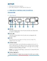
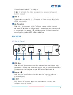
1

 USB Link

  This LED will illuminate when the transmitter has linked with 

receiver’s USB signal. 

2


Power LED


This LED will illuminate when the device is plugged with 

power supply.

3

 DC 5V

  Plug the 5V DC power supply into the unit and connect the 

adaptor to an AC outlet.

4

 Link Pair Select


This dip switch allows user with multi-pairs setting for link up to 16 

pairs of the devices with single IP router.  Each pair must have the 

same dip switch setting in order to pair to the right device setting. 

The factory default setting is at 0000.


Note:

 To activate the setting a re-power on is required after 

each new setting.  

5


Link On/Off button

  Press this button to allow the receiver to be link up or unlink 

Summary of Contents for CA-USBS100R

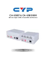
Page 1: ...Operation Manual Operation Manual CA USBST CA USBS100R USB over single CAT5e 6 Transmitter and Receiver ...

Page 2: ...rves the right to make improvements to this document and or product at any time and without notice COPYRIGHT NOTICE No part of this document may be reproduced transmitted transcribed stored in a retrieval system or any of its part translated into any language or computer file in any form or by any means electronic mechanical magnetic optical chemical manual or otherwise without express written per...

Page 3: ...s product Never push an object of any kind into this product through any openings or empty slots in the unit as you may damage parts inside the unit Do not attach the power supply cabling to building surfaces Use only the supplied power supply unit PSU Do not use the PSU if it is damaged Do not allow anything to rest on the power cabling or allow any weight to be placed upon it or any person walk ...

Page 4: ...ion 1 2 Applications 1 3 Package Contents 1 4 System Requirements 1 5 Features 1 6 Operation Controls and Functions 2 6 1 Front Panel 2 6 2 Front Panel 3 6 3 Rear Panel 4 7 Connection and Installation 5 8 Specifications 7 ...

Page 5: ... using ethernet hub in between to extend the distance double up to 200 meters The USB over CAT5e 6 transmitter and receiver boxes are the ideal choice for your USB extension needs 2 APPLICATIONS USB Extension over CAT5 6 up to 100M or 200M throu Hub Control devices from far away Host device information sharing and control 3 PACKAGE CONTENTS USB over CAT5e 6 Transmitter x 1 USB over CAT5e 6 Receive...

Page 6: ...r supply 3 DC 5V Plug the 5V DC power supply into the unit and connect the adaptor to an AC outlet 4 Link Pair Select This dip switch allows user with multi pairs setting for link up to 16 pairs of the devices with single IP router Each pair must have the same dip switch setting in order to pair to the right device setting The factory default setting is at 0000 Note To activate the setting a re po...

Page 7: ...mitter and receiver is connected the green LED will illuminate When the data is sending the yellow LED will be blinking RECEIVER 6 2 Front Panel 1 2 3 4 5 6 1 USB Link This LED will illuminate when the transmitter has linked with receiver s USB signal User are only able to control the USB in the source device when this LED is not illuminated 2 Power LED This LED will illuminate when the device is ...

Page 8: ...required after each new setting 5 USB Link button Press this button to allow the receiver to be link up or unlink with the transmitter s USB input Note To activate the link a re power on is required after each button pressed 6 CAT5e 6 Out This slot is to connect with CAT5e 6 cable with receiver side s CAT5e 6 input When both transmitter and receiver is connected the green LED will illuminate When ...
Page 9: ...5 7 CONNECTION AND INSTALLATION Flash MP4 Keyboard Mouse hard drive Scanner Printer Receiver Transmitter CAT5e 6 100m CAT5e 6 100m CAT5e 6 100m Internet Hub USB Example 1 Or Or ...

Page 10: ...6 Flash Keyboard HUB Scanner PC PC USB USB PC PC USB USB Example 2 Or Transmitter X 16 1 2 3 4 1 2 3 4 Receiver X 16 Mouse CAT5e 6 100m CAT5e 6 100m ...

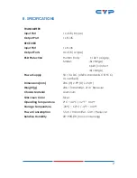
Page 11: ...discharge 6kV contact discharge Power Supply 5V 3A DC US EU standards CE FCC UL certified Dimensions mm 206 W x 99 D x 25 H Weight g 206 Transmitter 214 Receiver Chassis Material Aluminum Silkscreen Color Silver Operating Temperature 0 C 40 C 32 F 104 F Storage Temperature 20 C 60 C 4 F 140 F Power Consumption 5 5W Transmitter 12W Receiver Relative Humidity 20 90 RH non condensing ...

Page 12: ...Home page http www cypress com tw CYPRESS TECHNOLOGY CO LTD ...

Reviews: