background image

38

37

39

Side view

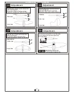
ELEVATOR

Adjust the travel of each control surface to the 
values in the diagrams.
These values fit general flight capabilities.
Readjust according to your needs and flight level.

Top view

36

AILERON

Adjustment.

Top view

Adjust the travel of each control surface to the 
values in the diagrams.
These values fit general flight capabilities.
Readjust according to your needs and flight level.

10

10

Adjustment.

Never fly before checking the Cg s required position.

In order to obtain the CG specified ,reposition the 
receiver and battery.

NEVER fly the model
 without well balancing.

Warning!

!

CG

Side view

Rudder

Adjust the travel of each control surface to the 
values in the diagrams.
These values fit general flight capabilities.
Readjust according to your needs and flight level.

Top view

150-160mm

150-160mm

Adjustment

Side view

Adjustment.

45

45

45

45

45

Flap

45

45

All manuals and user guides at all-guides.com

Summary of Contents for Spitfire MK IX

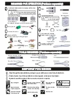
Page 1: ...is instruction manual ready at hand for quick reference even after completing the assembly lCould cause serious injury or even death SPECIFICATION Spitfire MK IX ALMOST READY TO FLY ALMOST READY TO FLY Before commencing assembly please read these instructions thoroughly Thank you for choosing CYmodel Global www cymodel com Australia www austars model com Italia www biellaexpress com Instruction Ma...

Page 2: ... radio may be used 12 AA size Batteries A minimum 6 channel transmitter for airplanes For handing the radio properly refer to its instruction manual Engine and Muffler Purchase a propeller that will match your engine Silicone Tube Fuel Filter required for engine starting Glow engine fuel only WARNING Normal gasoline cannot be used with glow engines Fuel Pump Plug Wrench Glue Instant glue Epoxy Glu...

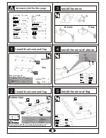
Page 3: ...od head 3X35mm screw 2X8mm screw 4 2 6 4 2 5X85mm rod 2 HORN 2 2 4X30 Screw 2 L L R R Flap Aileron A B A B 6 6 A B A B Make sure hinges are mounted in the same line 2 3X10mm Tp screw 8 L L R R Rod adjuster Connecting rod head 3X12mm TP screw 2X8mm screw 4 2 6 4 2 5X85mm rod 2 HORN 2 4X30 Screw 2 2 3X10mm Tp screw 8 Flap Aileron Tailing edge Aileron 4mm Servo line Rod adjuster Connecting rod head 3...

Page 4: ...ir line 2 Install the main landing gear Install the main landing gear Main wing installing Bottom L L R R 3X3mm screw 5 2mm Collar 3X20mm Tp screw 8 5X45mm Axletree 2 2 2 4X4mm screw 2 Install the main landing gear 4mm 4mm 4X35mm screw 4mm Washer 4 4 32X755mm Tube 20X55mm Tube L L R R Ply wood Ply wood 2 4 A B Main wing installing Top Servo line Servo line Air line Air line 3X3mm screw 5 2mm Colla...

Page 5: ...ccidents Warning Warning L L R R Bottom view L L R R make sure hinges are mounted in the same line Hinge 3 A B A B L L R R Rod adjuster Connecting rod head 3X30mm screw 2X8mm screw 4 2 6 4 2 5X85mm rod 2 HORN 2 2 4X40 Screw 2 make sure hinges are mounted in the same line A B Hinge 6 L L R R L L R R 3mm 3mm 3mm 3mm Servo line Rod adjuster Connecting rod head 3X30mm screw 2X8mm screw 4 2 6 4 2 5X85m...

Page 6: ...e Rudder 4mm A B 80mm spring 2 Install the servo of rudder tail wheel Install the servo of rudder tail wheel Install the servo of rudder tail wheel Aluminium tube Rod adjuster Connecting rod head 2X8mm screw 2 2 2 Rod 2 2 3mm nut 6 1400mm Steel wire 2 HORN 2 4X30 Screw 2 3X35mm screw 3 Aluminium tube Rod adjuster Connecting rod head 2X8mm screw 4 4 2 Rod 4 4 3mm nut 6 1400mm Steel wire 2 HORN 2 4X...

Page 7: ...lose control of your airplane which leads to accidents A A B B C C A A B B C C Main wing Horizontal Vertical tail Warning 8mm 8mm Main wing installing Installing the engine 50cc A B Throttle Throttle Fuel tank Fuel tank 4X20mm screw 4mm Washer 2 2 5X30mm screw 4 8X40mm Carbon tube 2 1 8X200mm Rod 1 Linkage Stopper 2mm Nut 1 1 3X3mm Screw 1 Install the throttle servo 1 8X200mm Rod 1 Linkage Stopper...

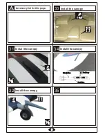
Page 8: ...cowling Receiver Receiver Battery Battery Battery Ignition Battery Ignition 3mm Bind nut 3mm Washer 6 6 3X16mm screw 6 3mm rubber band 6 6mm Plywood 6 Install the thr cowling A B Spinner Spinner Propeller Propeller 3mm Bind nut 3mm Washer 6 6 3X16mm screw 6 3mm rubber band 6 6mm Plywood 6 2 3X10 Tp screw 6 Cut away the surplus pats of canopy care fully along the shaded line Install the canopy 2 3X...

Page 9: ...l the canopy Install the canopy Install the canopy Install the canopy 5 0 2 C A C A A B L L R R 5 0 2 C A C A L L R R A B 5 0 2 C A C A Blcak line Blcak line Red line Red line 1 5V 1 5V 1 5V 1 5V Battery Battery All manuals and user guides at all guides com ...

Page 10: ...just according to your needs and flight level 10 10 Adjustment Never fly before checking the Cg s required position In order to obtain the CG specified reposition the receiver and battery NEVER fly the model without well balancing Warning CG Side view Rudder Adjust the travel of each control surface to the values in the diagrams These values fit general flight capabilities Readjust according to yo...

Reviews: