background image

5

V1.0

Installation

Read ‘Safety information’ before installing the fixture.

The fixture is designed for indoor use only and must be used in a dry location with adequate ventilation. 

Ensure that none of the fixture’s ventilation slots are blocked.

Fasten the fixture to a secure structure or surface. Do not stand it on a surface or leave it where it can 

be moved or fall over. If you install the fixture in a location where it may cause injury or damage if it falls, 

secure it as directed in this user manual using a securely anchored safety cable that will hold the fixture if 

the primary fastening method fails.

Fastening the fixture to a 

flat

 surface

The fixture can be fastened to a hard, fixed, 

flat

 surface that is oriented at any angle. Ensure that the sur-

face and all fasteners used can support at least 10 times the weight of all fixtures and equipment to be 

installed on it.

Fasten the fixture securely. Do not stand it on a surface or leave it where it can be moved or fall over. If 

you install the fixture in a location where it may cause injury or damage if it falls, secure it as directed be

-

low with a securely anchored safety cable that will hold the fixture if the primary fastening method fails.

Mounting the fixture on a truss

The fixture can be clamped to a truss or similar rigging structure in any orientation. When installing the 

fixture hanging vertically down, you can use an open-type clamp such as a G-clamp. When installing in 

any other orientation, you must use a half-coupler clamp that completely encircles the truss chord.

To clamp the fixture to a truss:

1. 

Check that the rigging structure can support at least 10 times the weight of all fixtures and equipment 

to be installed on it.

2.  Block access under the work area.

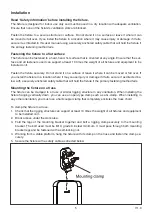
3.  Fold the legs of the mounting bracket together and bolt a rigging clamp securely to the mounting 

bracket. The bolt used must be M10, grade 8.8 steel minimum. It must pass through both mounting 

bracket legs and be fastened with a self-locking nut.

4. 

Working from a stable platform, hang the fixture with its clamp on the truss and fasten the clamp se

-

curely.

5. 

Secure the fixture with a safety cable as directed below.

Summary of Contents for FR-300C

Page 1: ...USER MANUAL FR 300C 300 watts Cool White LED Fresnel...

Page 2: ...ble 6 DMX 512 connection connection between fixtures 6 Art Net Connection 7 Power connection 7 Operation 8 Control Menu Map 8 Control menu 9 Main Menu 9 Addressing 9 Universal DMX Control 10 RDM contr...

Page 3: ...the housing can become hot during operation After use wait for a cool down period of at least 10 minutes before handling or transporting the device Every person involved with the installation operati...

Page 4: ...door and color frame holder Handle Net out LCD display Menu button Up button Down button Enter button Net in Fuse Power in On off switch Safety cable anchor point Dmx out Dmx in Dmx signal indicator...

Page 5: ...l over If you install the fixture in a location where it may cause injury or damage if it falls secure it as directed be low with a securely anchored safety cable that will hold the fixture if the pri...

Page 6: ...DMX chain If you wish to connect DMX controllers with other XLR outputs you need to use adapter cables Building a serial DMX chain Connect the DMX output of the first fixture in the DMX chain with the...

Page 7: ...equirements The FR 300C LED zoom luminaire operates on 100 to 240 volts AC 10 auto ranging The lumi naire contains an auto ranging power supply Power linking between fixtures The fixture with powercon...

Page 8: ...e ArtNet Net 000 127 Set Art Net net SubNet 000 015 Set Art Net subnet in Art Net net Universe 000 015 Set Art Net universe in Art Net subnet Channel 1 2 3 4CH Art Net channel mode Auto Program 001 00...

Page 9: ...Control menu The information menu will appear after the fixture is switched on In this menu the following status is dis played Main Menu Press the MENU button to enter the Main Menu interface Address...

Page 10: ...e If you set for example the ad dress in the 1 channel mode to channel 2 the device will use the channel 2 for control Note After switching on the device will automatically detect whether DMX 512 data...

Page 11: ...pose is to allow transfer of large amounts of DMX 512 data over a wide area using standard network technology Art Net designed by and copyright Artistic Licence Holdings Ltd For more detail explainati...

Page 12: ...ect Mode menu and press ENTER 3 Press DOWN menu and select Manual sub menu 4 Press ENTER and select Zoom in third menu 5 Rotate the rotary knob to control the dimmer right stop minimum zoom scale left...

Page 13: ...or DOWN button to select Dimmer menu and press ENTER 3 Press DOWN menu and select Mode sub menu 4 Select disired dimmer mode Custom dimmer curves 1 Press the MENU button to enter the main menu 2 Press...

Page 14: ...55 Zoom from wide to narrow Fixture Cleaning Due to fog residue smoke and dust cleaning the internal and external optical lenses and mirror should be carried out periodically to optimize light output...

Page 15: ...der next to the MAINS OUT socket on the connections panel To replace a fuse 1 Disconnect the fixture from power and allow it to cool for at least 10 minutes 2 Unscrew the cap of the fuseholder and rem...

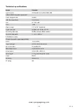
Page 16: ...8 500 Lux 5m 15 Control protocols RDM Artnet DMX control Control channels 1 2 3 4 CHs 5 Dimmer curves Flicker free with selectable PWM Color Cool white Input voltage AC100 240V 50 60Hz AC connection P...

Reviews: