CyberResearch UCERB 24 User Manual Download Page 23

USB LED 

The 

USB

 LED indicates the communication status of the 

UCERB 24

. It uses up to 5 mA of current and 

cannot be disabled. Ta

 explains the USB LED function. 

ble 3-2

Table 3-2. USB LED Illumination 

USB LED 
illumination 

Indication 

Steady green 

The 

UCERB 24

 is connected to a computer or external USB hub. 

Pulsing green 

Initial communication is established between the 

UCERB 24

 and the computer, or data is 

being transferred. 

PWR LED 

The 

UCERB 24

 incorporates an on-board voltage supervisory circuit that monitors the external 9 V 

power. If the input voltage falls outside of the specified range, the 

PWR

 LED shuts off. 


explains the function of the PWR LED.  

Table 3-3

Table 3-3. PWR LED Illumination 

PWR LED 
illumination 

Indication 

Steady green 

External power is supplied to the 

UCERB 24.


Off 

Power is not supplied by the external supply, or a power fault has occurred. A power fault 
occurs when the input power falls outside of the specified voltage range of the external supply 
(6.0 V to 12.5 V). 

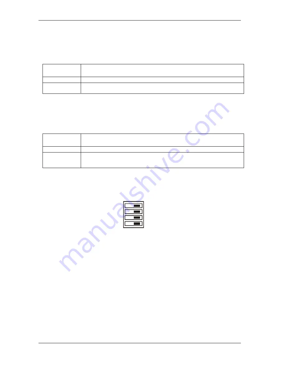
Invert/non-invert switch (S1) 

The Invert/non-invert switch (S1) sets the relay control logic per relay bank to either inverted or non-
inverted. By default, switch S1 is configured for non-invert (see 

)

Figure 3-2

Figure 3-2. Switch S1 default configuration 

NON-INVERT

INVERT

S1

CL
CH

A
B


The switch labeled 

A

 configures relays 1 through 8, the switch labeled 

B

 configures relays 9 through 16, 

the switch labeled 

CH

 configures relays 17 through 20, the switch labeled 

CL

 configures relays 21 

through 24. 

ƒ


NON-INVERT

: when "0" is written or read back via the USB bus, the relays are not energized. 

ƒ


INVERT

: when "0" is written or read back via the USB bus, the relays are energized. 

Switch settings do not affect the power-on condition. Use 

Insta

Cal to read the current logic setting for 

each module group. 

CyberResearch

® 

Digital I/O 


UCERB 24 


CyberResearch, Inc

.                                                                                                                                 

1

5

25 Business Park Drive 


P: (203) 483-8815; F: (203) 483-9024 

Branford, CT USA 


www.cyberresearch.com 


Summary of Contents for UCERB 24

Page 1: ...nual may be reproduced without permission UCERB 24 USB Electromechanical Relay Module 24 SPDT Form C Relays with 24 Screw Terminals CyberResearch Inc www cyberresearch com 25 Business Park Dr Branford...

Page 2: ......

Page 3: ......

Page 4: ......

Page 5: ...Research and UCERB 24 are trademarks of CyberResearch Inc Other product names mentioned herein are used for identification purposes only and may be trademarks and or registered trademarks of their res...

Page 6: ...UCERB 24 CyberResearch Digital I O iv Copyright 2005 CyberResearch Inc Intentionally Blank...

Page 7: ...6 Configuring the hardware switches 6 Connecting the external power supply 7 Connecting the UCERB 24 to your system 8 Installing the software 9 Chapter 3 Functional Details 14 Internal components 14 U...

Page 8: ...UCERB 24 CyberResearch Digital I O vi Copyright 2005 CyberResearch Inc...

Page 9: ...ts present information to help you avoid injuring yourself and others damaging your hardware or losing your data Angle brackets that enclose numbers separated by a colon signify a range of numbers suc...

Page 10: ...ectly to the board s screw terminals The screw terminals provide three connections to each relay normally open NO normally closed NC and common C You can configure the logic polarity and power on stat...

Page 11: ...elay 10 Relay 9 Relay 8 Relay 7 Relay 6 Relay 5 Relay 4 Relay 3 Relay 2 Relay 1 NO C NC C NO C NC C NO C NC C NO C NC C NO C NC C NO C NC C NO C NC C NO C NC C NO C NC C NO C NC C NO C NC C NO C NC C...

Page 12: ...required You can connect the UCERB 24 before or after you install the software and without powering down your computer first When you connect an HID to your system your computer automatically detects...

Page 13: ...ERB 24 External power supply and cord 9 volt 3 amp DC power supply USB cable 2 meter length Software The CyberResearch Software CD contains the InstaCal installation calibration and test utility Unive...

Page 14: ...igure these switches before you connect the external power supply to the UCERB 24 Factory configured default settings are listed in Table 2 1 Refer to Figure 3 1 for the location of each switch on the...

Page 15: ...SB bus the relays are energized Switch settings for polarity can be read back via software through the USB bus Switch settings for S1 do not affect the power on condition Relay power on state Configur...

Page 16: ...r dialog other Windows versions opens as the UCERB 24 is detected When this balloon or dialog closes the installation is complete The USB LED should flash and then remain lit This indicates that commu...

Page 17: ...ation refer to the Microsoft Knowledge Base article Availability of the Windows XP SP1 USB 1 1 and 2 0 update This article is available at support microsoft com kbid 822603 1 Close all applications yo...

Page 18: ...ton To bypass installing the NET Framework 1 1 click on the No button We strongly recommend that you install the Microsoft NET Framework 1 1 The DAQ software installer program and some DAQ software co...

Page 19: ...llation Information dialog opens 3 Read the information on this dialog If a warning dialog opens during this installation asking to allow scripts to run click the appropriate option that allows them t...

Page 20: ...is license agreement option and then click on the Next button The Ready to install the programs dialog opens 6 Click on the Install button The Installing DAQ Software dialog opens and stays open while...

Page 21: ...Restart your computer Installing UL or UL for LabVIEW If you are going to install the Universal Library or Universal Library for LabVIEW you can install either of the packages before you restart Unpac...

Page 22: ...ure The USB OUT connector is a downstream hub output port intended for use with other CyberResearch products only The USB hub is self powered and can provide 100 mA maximum current at 5 V For informat...

Page 23: ...ed A power fault occurs when the input power falls outside of the specified voltage range of the external supply 6 0 V to 12 5 V Invert non invert switch S1 The Invert non invert switch S1 sets the re...

Page 24: ...e voltages Use 12 22 AWG wire for your signal connections Properly insulate the wires to avoid any short circuit to the other channels ground or other points on the board Caution Keep the length of st...

Page 25: ...that you connect The UCERB 24 is powered with a 9 VDC nominal 3 0 A external power supply Voltage drop A drop in voltage occurs with each board connected in a daisy chain system The voltage drop betw...

Page 26: ...l down user installed Relay contact protection circuit for inductive loads When you connect an inductive load to a relay energy stored in the inductive load can induce a large voltage surge when you s...

Page 27: ...ion mechanical operations min S2 pull up Energized NO in contact with Common Power on state S2 pull down Not energized NC in contact to Common Relay control logic polarity User configurable per bank v...

Page 28: ...On External power adapter included 9 V 10 3 A Note 1 The UCERB 24 monitors the external 9 V power supply voltage with a voltage supervisory circuit If this power supply exceeds its specified limit the...

Page 29: ...R112 R114 R116 R118 Relays NO contact pull up to USB 5 V pull down user installed R37 R40 R42 R44 R46 R48 R50 R52 R88 R90 R92 R94 R95 R97 R99 R101 R104 R106 R108 R110 R111 R113 R115 R117 Relays NC co...

Page 30: ...Normally Open contact 11 NC Relay 11 Normally Closed contact 11 C Relay 11 Common contact 11 NO Relay 11 Normally Open contact 12 NC Relay 12 Normally Closed contact 12 C Relay 12 Common contact 12 NO...

Page 31: ...mally Closed contact 23 C Relay 23 Common contact 23 NO Relay 23 Normally Open contact 24 NC Relay 24 Normally Closed contact 24 C Relay 24 Common contact 24 NO Relay 24 Normally Open contact CyberRes...

Page 32: ...UCERB 24 CyberResearch Digital I O 24 Copyright 2005 CyberResearch Inc...

Page 33: ...ings and possibly change settings before reinstalling the modules 3 Have a volt meter handy to take measurements of the signals you are trying to measure as well as the signals on the board module or...

Page 34: ...UCERB 24 CyberResearch Digital I O 26 Copyright 2005 CyberResearch Inc Intentionally Blank...

Page 35: ...the sole and exclusive liability of the Seller its successors or assigns in connection with equipment purchased and in lieu of all other warranties expressed implied or statutory including but not li...

Page 36: ...UCERB 24 CyberResearch Digital I O 28 Copyright 2005 CyberResearch Inc Intentionally Blank...

Page 37: ......

Page 38: ...CyberResearch Inc 25 Business Park Drive Branford CT 06405 USA P 203 483 8815 F 203 483 9024 www cyberresearch com...

Reviews: